An Inside Look at High-Speed ADC Accuracy, Part 2
This file type includes high resolution graphics and schematics when applicable.

looked at general static analog-to-digital converter (ADC) inaccuracy errors and ADC inaccuracy error that involves bandwidth. Hopefully, it also provided a greater understanding of ADC errors and how these errors influence the signal chain. With that, keep in mind that not all components are created equal, whether you’re talking active or passive devices. Thus, there will be errors within the analog signal chain, regardless of what is down-selected as the final part to fit into the system.
This article describes the differences between accuracy, resolution, and dynamic range. It also reveals how inaccuracies accumulate within the signal chain and cause errors. This plays an important role in understanding how to specify or choose an ADC properly when defining system parameters for a new design.
Accuracy vs. Resolution vs. Dynamic Range
Many users of converters seem to use the terms accuracy and resolution interchangeably. However, this is a mistake. The terms accuracy and resolution are not equal but are related. Therefore, they should not be used interchangeably. Think of accuracy and resolution as, say, cousins, but not twins1 please.
Accuracy is simply error, or how much the value under measurement deviates from its true value. Accuracy error can also be referred to as sensitivity error. Resolution is simply how finely the value measured can be represented or displayed. Even though a system may have 12 bits of resolution, it doesn’t mean it will be able to measure a value to 12 bits of accuracy.
For example, say a multimeter has six digits to represent a measurement. This multimeter’s resolution is six digits, but if the last one or two digits seem to “flicker” between measurement values, then the resolution is compromised and so is the accuracy of the measurement.
The errors in any system or signal chain accumulate throughout, distorting the original measurement taken. Therefore, it’s also important to understand the dynamic range of the system in order to gauge the accuracy and the resolution of the signal chain under design.
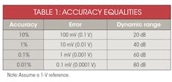
Let’s look again at the multimeter. If there are six digits of representation, then the dynamic range of this device should be 120 dB (or 6 × 20 dB/decade). Keep in mind, though, that the bottom two digits are still flickering. Therefore, the real dynamic range is only 80 dB. That means if the designer intends to measure a 1 µV (or 0.000001 V), the error involved in this measurement could be off as much as 100 µV, since the actual device is only accurate to 100 µV (or 0.0001 V or 0.0001 XX V, where XX represents the bottom two digits flickering).
Effectively, any system’s overall accuracy can be described in two ways: dc and ac. With regard to dc accuracy, it represents the “deviated” accumulation of error as shown throughout a given signal chain. This is sometimes termed as a “worst-case” analysis. The noise-error terms that accumulate throughout the signal chain is a measure of ac accuracy. This defines the signal-to-noise ratio (SNR) of the system. These errors then add up, lowering the SNR and yield a more true effective number of bits (ENOB) of the entire design. Obtaining both parameters effectively tells the user how accurate the system can be with both static/wondering and dynamic signals.
How Do Low-Frequency SNR, ENOB, Effective Resolution, and Noise-Free Code Resolution Relate?
Remember, an ADC can “take in” many types of signals that are typically classified as either dc or ac and quantify it digitally. Understanding the ADC’s error in the system means the designer must understand the type(s) of signals that will be sampled. Therefore, depending on the signal type depends on the way to define the converter’s error contribution to the overall system. These converter errors are generally defined in two ways: noise-free code resolution, representing dc-type signals; and the “SNR equation,” representing ac-type signals.
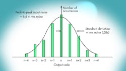
All active devices, such as ADC internal circuits, produce a certain amount of rms noise due to resistor noise and "kT/C" noise. This noise is present even for dc-input signals, and accounts for the code transition noise in the converter’s transfer function. This is more commonly referred to as input-referred noise. The most common way to characterize input-referred noise is by examining the histogram of a number of output samples when applying a dc input to the converter.
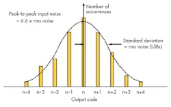
The output of most high-speed or high-resolution ADCs is a distribution of codes, centered around the nominal value of the dc input. To measure its value, the input of the ADC is either grounded or connected to a heavily decoupled voltage source, and a large number of output samples are collected and plotted as a histogram (sometimes referred to as a grounded-input histogram) (Fig. 1). Since the noise is approximately Gaussian, the standard deviation of the histogram, σ, can be calculated, corresponding to the effective input rms noise and expressed in terms of LSBs rms.
Although the inherent differential nonlinearity (DNL) of the ADC may cause some minor deviations from an ideal Gaussian distribution, it should be at least approximately Gaussian. If the code distribution has large and distinct peaks and valleys, this could be the indication of a bad printed-circuit-board (PCB) layout, poor grounding techniques, or improper power-supply decoupling among other things...
Typically, input-referred noise can be expressed as an rms quantity, usually having the units of LSBs rms. Specifications involving these types of quantities are more generally associated with high-resolution precision-type converters, because of the low sample rates and/or dc-type or slow-moving signals acquired by them.
Sigma-delta ADCs designed for precision measurements, having resolutions in the 16- to 24-bit range, have datasheet specifications such as input-referred noise, effective resolution, and noise-free code resolution to describe their dc dynamic range. On the other hand, higher-frequency sigma-delta ADCs for audio applications are generally characterized exclusively in terms of total harmonic distortion (THD) and total harmonic distortion plus noise (THD + N).
Successive-approximation-register (SAR) converters cover a wide range of sampling rates, resolutions, and applications. They typically have the input-referred noise specification, but also maintain specifications for SNR, ENOB, SFDR, THD, etc., for ac input signals.
Although higher-speed converters (such as pipelined) that sample in the hundreds of megahertz or beyond are typically specified in terms of ac specifications such as SNR, SINAD, SFDR, and ENOB, they can also capture dc-type or slow moving signals. It’s therefore useful to understand how to derive the low-frequency performance of high-speed converters from the ac specifications given on the datasheet (see “Signal-to-Noise Ratio (SNR) Equation").
Relating both slow-speed, dc-type signals, and high-speed, ac-type signal specification quantities does requires some math. So break out your college math book and flip to the identity table in the back and let’s review below how a relation can be struck between SNR, ENOB, effective resolution, and noise-free code resolution for low-frequency inputs.
With FSR = full-scale range of ADC, and n = input-referred noise, (rms) effective resolution is defined as the following:
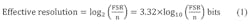
Note that log2(x) = log10(x) ÷ log(2) = log10(x) ÷ 0.301 = 3.32 × log10(x)
Therefore,

or


Therefore,
Rearranging this a bit, we get:
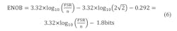
This yields the following:
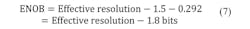
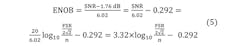
Therefore, by substituting in Equation 7, we can derive the relationship between ENOB, ac-type signals, and dc-type (slow moving) signals, or:

To verify this, let’s calculate the ENOB for ideal N-bit ADC, where:

Substituting in these values,
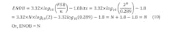
To summarize, when looking at dc (slow-moving) signals, the ENOB of the system is roughly 1 bit larger (0.92 bits to be exact) than the converter’s noise-free code resolution and 2 bits less than its effective resolution.
However, as the signals move faster (ac-type signals) where bandwidth is involved, the converter’s SNR and the ENOB become frequency-dependent and typically degrade for higher-frequency inputs.
Converter Inaccuracies in a Signal Chain
Now that the converter errors are understood, the rest of the signal chain is applied to understand these concepts at the system level. Figure 2 describes an example of a simple data-acquisition signal chain. Here, a sensor is connected to a long amount of cable that ultimately gets connected to the data-acquisition card. The sensor’s ac signal pushes through two stages of preconditioning amplifiers before arriving at the ADC’s inputs to be sampled. The goal here is to design a system that can accurately represent a sensor’s signal within ±0.1% of its original value. Hmmm…sound challenging?
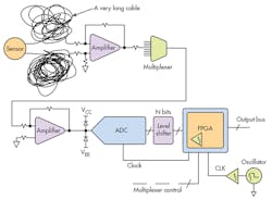
To design such a system, it’s important to think about the types of errors that could be affecting the sensor’s original signal and where they are coming from throughout the signal chain. Imagine what the converter sees in the end when the signal is finally sampled.
Let’s suppose the ADC has a 10-V full-scale input and 12 bits of resolution in this example. If the converter were ideal, it could be determined that it has a dynamic range or SNR of 74 dB:

However, the datasheet specifications only show the converter to have an SNR of 60 dB or 9.67 ENOB:

Please note the calculation of SNR and ENOB—when calculating ENOB from an SNR number in the datasheet, it should be clear to the designer that this may or may not include harmonics. If it does include distortion, then SINAD can be used, which is defined as SNR + distortion, or sometimes referred to as total harmonic distortion (THD).
Therefore, the LSB size can be defined as 12.2 mV p-p or VFS/2N = 10/29.67. This dramatically reduces the number of representations that can occur on the digital outputs. Remember, the bottom LSBs/bits are flickering because of the noise in the ADC:

This also means the converter has an accuracy of ±6.12 mV or 0.0612%:

Additionally, this implies that for a 1.00000-V input applied to the converter, the output can be between 0.99388 and 1.00612 V.
Therefore, the 12-bit converter with 9.67-bit ENOB can only measure a signal to 0.1% accuracy. The converter’s dynamic range is approximately 60 dB, rather than 74 dB (ideal 12-bit ADC):

This can be seen in Figure 3. Table 1 describes some quick equalities for referencing desired system performance.
Converter Inaccuracies in a Signal Chain
Be mindful of all the front-end components as suggested in the above signal-chain example. Just because the converter accuracy meets or beats the system accuracy specification defined for the system, there are still more inaccuracies to comprehend, i.e., the front-end, power supply, any other outside influences, or environments.
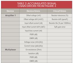
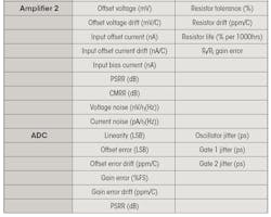
The design of such a signal chain as described in Figure 2 can be very intense and is beyond the scope of this paper. However, Table 2 offers a quick view on inaccuracies/errors associated with such a signal chain.
Many errors are present in any signal chain, not to mention the cable and other outside influences that can also play a big role in determining the design of such a system. Whatever the error accumulation, it ultimately gets sampled at the converter along with the presence of the signal—assuming the error is not great enough to mask the signal that is being acquired!
When designing with converters, keep in mind there are two parts to the equation when it comes to defining the accuracy of the system. There’s the converter itself, as described above, and everything else used to precondition the signal before the converter. Remember, every bit lost causes a 6-dB decrease in dynamic range. The corollary—for every bit gained, the system’s sensitivity increases by 2X. Therefore, the front-end requires an accuracy specification to be much better than the converter’s accuracy chosen to sample the signal.
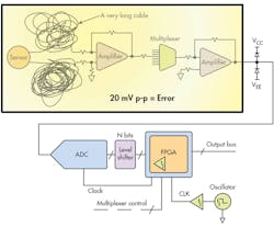
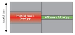
To illustrate this point, using the same front-end design shown in Figure 2, let’s say the front-end itself has 20 mV p-p of inaccuracies, i.e., accumulated noise (Fig. 4). The system accuracy is still defined as 0.1%. Is the same 12-bit converter going to have enough accuracy to maintain the system specification defined? The answer is no, and here’s why.
It can be figured out by using the ADC that has a SNR = 60 dB:

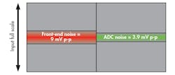
Notice that 20 mV of noise can degrade the system by 1 bit or 6 dB, bringing the performance down to 54 dB from 60 dB, which was originally described as the system’s performance requirement. To get around this, maybe a new converter should be chosen in order to maintain the 60 dB or 0.1% system accuracy. Let’s choose an ADC that has 70 dB of SNR/dynamic range or an ENOB of 11.34 bits to see if this works.

It appears that the performance didn’t change much. Why? The reason is that noise of the front end is too great to comprehend 0.1% accuracy, even though the converter’s performance itself is much better than the specification. The front-end design thus needs to change in order to get the desired performance. This is represented figuratively in Figure 5. See why this last configuration example won’t work? The designer can’t simply pick a better ADC to improve the overall system performance.
Bringing It All Together
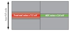
The previously chosen 10-V full-scale, 12-bit ADC has a dynamic range of 60 dB to achieve 0.1% accuracy. This means a total accumulated error of <10 mV or 10 V/(1060/20) needs to be met to reach 0.1% requirement. Therefore, the front-end components have to change to reduce the front-end error down to 9 mV p-p (Fig. 6), using a converter that has 70 dB of SNR.
If the 14-bit, 74-dB ADC was to be used (Fig. 7), then the front-end’s requirements can be relaxed even further. However, tradeoffs can have an upside in cost. These tradeoffs need to be evaluated per the design and application. It may be worth paying more for tighter tolerance and lower drifting resistors than to splurge for a higher-performing ADC, for example.
Concluding the Analyses
The following should have provided some guides on how accuracy error, resolution, and dynamic range are all related, but offer different points when selecting a converter for any application that requires a certain amount of measurement accuracy. It’s important to understand all component errors and how those errors influence the signal chain. Keep in mind that not all components are created equal.
Developing a spreadsheet that captures all of these errors is an easy way to plug in different signal-chain components to make evaluations and component tradeoffs quickly (Table 2, again). This is especially true when trading off costs between components. Further discussions on how to go about generating such a spreadsheet will be covered in Part 3 of this series.
Finally, remember that simply increasing the performance or resolution of the converter in the signal chain will not increase the measurement accuracy. If the same amount of front-end noise is still present, the accuracy will not improve. Those noises or inaccuracies will only be measured to a more granular degree and it will cost the designer’s boss more money in the end to do it...
Reference:
1. “Resolution and Accuracy: Cousins, not Twins,” John Titus, Design News, 5/5/2003.
Other reading:
Signal Conditioning & PC-Based Data Acquisition Handbook, John R. Gyorki, 3rd Edition, 1-11.
“AN010: Measurement Dynamic Range for Signal Analyzers,” LDS Dactron, 2003.
“System Error Budgets, Accuracy, Resolution,” Dataforth.
“Overall Accuracy = ENOB (Effective Number of Bits),” Data Translation.
Analog-Digital Conversion: Seminar Series, Walk Kester, Walt Kester, Analog-Digital Conversion, Analog Devices, 2004, ISBN 0-916550-27-3. Also available as The Data Conversion Handbook, Elsevier/Newnes, 2005, ISBN 0-7506-7841-0
W. R. Bennett, "Spectra of Quantized Signals," Bell System Technical Journal, Vol. 27, July 1948, pp. 446-471.
W. R. Bennett, "Noise in PCM Systems," Bell Labs Record, Vol. 26, December 1948, pp. 495-499.
Steve Ruscak and Larry Singer, “Using Histogram Techniques to Measure A/D Converter Noise,” Analog Dialogue, Vol. 29-2, 1995.
Brad Brannon, "Overcoming Converter Nonlinearities with Dither," Application Note AN-410, Analog Devices, 1995.
About the Author

Rob Reeder
Application Engineer, High-Speed Converters, Texas Instruments
Rob Reeder is currently the application engineer for High-Speed Converters at Texas Instruments (TI) in Dallas. Rob’s prior experience includes RF design at Raytheon Missile Systems in Tucson, Ariz., including analog receivers and signal-processing applications. He was also a system application engineer with Analog Devices in the High-Speed Converter and RF Applications Group in Greensboro, N.C., for over 20 years.
He has published over 130 articles and papers on converter interfaces, converter testing, and analog signal chain design for a variety of applications. Rob received his MSEE and BSEE from Northern Illinois University in DeKalb, Illinois, in 1998 and 1996, respectively. When Rob isn’t writing papers late at night or in the lab hacking up circuits in the lab, he enjoys hanging around at the gym, listening to EDM, building rustic furniture out of old pallets, and, most importantly, chilling out with his family.
Comment About the Article
To join the conversation, and become an exclusive member of Electronic Design, create an account today!

Leaders relevant to this article: