What you'll learn:
- Fully integrated class-D amplifiers.
- Class-D amplifiers are just filtered PWM.
- Class-D amplifier filter design considerations.
This article was originally published in the Dec 14, 1998 issue of Electronic Design.
Class-D audio power amplifiers (APAs) were first introduced nearly 50 years ago. Since then, they have been used sparingly in a relatively small number of applications with limited bandwidth, such as public address systems and telephony equipment. This will soon change as a new class of integrated Class-D APAs make their way into such mainstream applications as portable computers, battery-operated music systems, wireless communication devices, and other compact low-power systems.
It's becoming clear that moving to next-generation designs requires taking advantage of this technology's greater power efficiency and its resulting reduction in heat dissipation. The bottom line is that Class-D amplifiers have the potential to reduce system size and cost while extending the life of battery-powered systems.
Fully Integrated Class D Amplifiers
Only recently have advances in semiconductor fabrication processes made integrated Class-D audio amplifiers possible. Fast-switching, rugged DMOS power MOSFETs can now be integrated with analog circuitry, eliminating the need for a discrete output power stage. The resulting Class-D APA is an effective, highly efficient solution for compact, battery-powered audio applications in the music bandwidth.
In a laboratory test designed to compare the power efficiency of Class-AB and Class-D APAs, a Class-D amplifier extended the life of a battery by 2.5 times. The test took a linear Class-AB APA and placed it on an evaluation platform in a test system with bass/treble volume control modules, dc-dc converter modules, and one 9-V alkaline battery. The test system ran until the dc/dc converter tripped its undervoltage lock-outlockout at 5.2 V. Subsequently, the voltage in the battery would drift upwards and the system would turn on again. After three such incidents, the test was deemed complete. Then, a Class-D APA was substituted for the Class-AB amplifier and the same procedure was repeated.
It's important to note that the test utilizes a real-world signal. Music was used instead of the sine waves or tones that are typically used in a lab to assess the power efficiency of audio amplifiers. Unlike the widely varying and often unruly music signals, tones are uniform and well behaved. In other words, the crest factor of music is much higher than that of a tone.
Using Crest Factor Crest factor can be used to analyze the differences between the amplifiers. Essentially, crest factor represents the difference between a signal's peaks and its RMS power:
Crest factor = 10 log (PPK/PRMS)
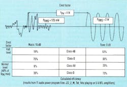
This is sometimes referred to as headroom. Music signals can have crest factors as high as 15 dB, which means that peaks of over 30 times the RMS value can occur. There is a dramatic difference in test results when music signals rather than sine waves are used to determine the power-efficiency of Class-AB and Class-D amplifiers (Fig. 1).
The simulations outlined in Figure 1 were done at full power, which occurs when the input signal is large enough to drive the output to the rails without clipping. The results are even more dramatic when the same simulation is done at normal listening levels, which are usually much less than full power. At less-than-maximum power, the efficiency of linear amplifiers drops considerably faster than does the efficiency of Class-D devices. These simulation results support the empirical battery-life tests that found that Class-D APAs are two to three times more power efficient than linear devices.
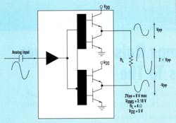
Basically, an audio power amplifier is a special type of operational amplifier optimized to drive low-impedance loads—typically speakers or headphones—at frequencies in the 20-Hz to 20-kHz range. Consider the architecture of a typical Class-AB linear APA used in a bridge-tied-load (BTL) configuration (Fig. 2). The input capacitor forms an RC high-pass filter with the input resistance of the amplifier, and attenuates signals below 20 Hz.
Linear amplifiers derive their name from the fact that they produce an instantaneous output that's equal to a given input multiplied by a constant, known as the gain of the amplifier. This requires that the output transistors be biased to operate in the linear region. The output transistors are analogous to variable resistors in which the input voltage adjusts the resistance to create the required output voltage. The output voltage of an amplifier must be derived from the supply voltage, with the difference being dropped across one of the device's output transistors to attain the output voltage level.
Linear Amps Always "On" Even when there is no input signal present, the output transistors are on and drawing precious quiescent current. This results in inefficient power dissipation and the generation of a great deal of heat. Heat sinks are required to transfer the excess heat to the ambient air.
The only way to improve the power efficiency of such an APA is to operate the output transistors as switches rather than as variable resistors. This means that when the output transistors are turned on, current is passed through the circuit but very little voltage is developed across it. When the switches are off, the circuit has the full supply voltage across it and virtually no current, minimizing I2R power losses. This type of switching arrangement is precisely how Class-D APAs operate.
Class D Amplifiers are just Filtered PWM
So a Class-D amplifier is essentially a switch-mode power delivery circuit, much like the switch-mode voltage regulators that are found in most personal computers. Rather than using a dc reference to set the output voltage, as switch-mode regulators do, Class-D amplifiers use the audio input signal as the reference.
Class-D APAs rely on a technique known as pulse width modulation (PWM) to sample the input signal and then recreate it as an audio signal at the load. PWM resembles digital data in that it has an on state and an off state. With PWM, a wider time pulse will represent a signal with greater amplitude. These pulses are used to modulate the power FETs on and off so that power is efficiently delivered from the power supply to the load. An output filter smoothes the Class-D amp's PWM output back into an analog waveform that is sent to the speaker.
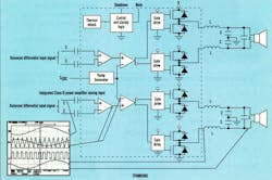
In a Class-D APA using linear PWM, a square-wave signal with a 50% duty cycle and a frequency much higher than the audio is fed into an integrator to create a triangle waveform at the same frequency (Fig. 3). A comparator then compares the triangle wave with the audio input signal to create a variable-duty-cycle square wave. In effect, a pulse-train is created with a duty cycle proportional to the audio signal level. These pulses then turn the output transistors on and off at a frequency that's much greater than that of the audio input frequency. Finally, a passive inductor-capacitor (LC) low-pass filter is used to remove the high-frequency content of the output signal so that only an amplified version of the input signal is delivered to the load.
The architecture shown in Figure 3 is of an integrated Class-D APA. More specifically, DMOS power FETs are integrated on the same piece of silicon as the analog circuitry. This integration reduces the size of the output drive circuit, saving space and decreasing the number of components.
It's important to have a stable power supply, a linear triangle signal, and an accurate and fast voltage comparator to minimize the PWM's distortion level. Feedback can be taken from the output of the PWM just prior to the low-pass filter with little difficulty.
System Design Issues With a Class-D APA, the layout of the pc board is critical to the overall performance of the amplifier and the entire system. Faulty layout practices can affect the system's total harmonic distortion and noise by orders of magnitude. Electromagnetic interference (EMI) also can be minimized with care and forethought.
Adding decoupling capacitors close to the power supply and locating high-frequency bypass capacitors close to the power pins will reduce noise from the supply and help provide current to the amplifier. It's especially important to filter the analog sections of the amplifier because any noise and distortion in this stage will be amplified in the output stage. The input circuitry should be isolated as much as possible from the output circuit, with care taken to avoid ground loops. Adherence to these and other current layout standards will minimize the distortion introduced by the input power and ground loops.
Another aspect of board layout that is central to an effective audio system using Class-D amplifiers is the use of a demodulation filter. This low-pass filter, which removes the high-frequency carrier (the PWM signal) from the amplified audio signal, must be properly located in order to ensure effectiveness.
If the Class-D APA output is configured as an H-bridge or full-bridge, a low-pass filter must be used on both outputs. The designer can use a simple passive LC arrangement (Fig. 3, again). The filter should have a maximally flat magnitude response within the passband, which results in minimal ripple. Ripple would reduce the dynamic swing of the output, lowering the crest factor and introducing asymmetric distortion in the output. The corner frequency is set by the equation:
F0 = 1/(2¼LC)
This is a second-order filter, characterized by a −40-dB per decade attenuation of the output above the corner frequency. As frequency is increased by a factor of 10, the inductive impedance increases by a factor of 10 and the capacitive impedance decreases by a factor of 10. Because the inductor blocks high frequency and the capacitor readily passes it, these factors multiply and the effect is to decrease the high-frequency component seen by the load by a factor of 100 (−40 dB) per decade.
Class D Amplifier Filter Design Considerations
Designers must consider a number of issues when creating this filter. They can increase the filter order by two for each LC combination added. The choice of components and the order of the filter will depend on the switching frequency, since the filter's sole purpose is to remove the switching frequency component from the output. This, in effect, averages the output pulse over one duty cycle. To accurately represent it at the output, the switching frequency should then be much higher than the audio input waveform's highest frequency component. There is a trade-off, however, in that as the switching frequency increases, the switching losses increase as well, reducing the efficiency of the amplifier.
Careful consideration should be given to the low-pass filter because peaking will occur at F0 when a speaker, which is reactive instead of purely resistive, is placed at the output. Placing a dampening resistor in series with a capacitor across the load or speaker can reduce the peaking.
Power losses also must be taken into consideration during the design of the low-pass filter. Because the inductor is in series with the power signal path, the series resistance of the inductor will reduce the power delivered to the speaker, decreasing the efficiency of the amplifier. The use of low-resistance inductors will lessen this problem.
Inductor Saturation The inductors' saturation current also is critical. If the inductor saturates during operation, it looks like a short and will not influence the output signal. As a result, distortion will substantially increase. In the case of a BTL configuration, the inductors' tolerance should be tight for good matching. The capacitors' tolerance should also be tight. Variations in these components can lead to increased harmonic distortion and reduced filter performance through changes in the frequency response.
The filter also contributes a portion of the quiescent current used by the Class-D APA. Because the output of a Class-D amplifier's H-bridge is a switching signal, the capacitors in the filter are either partially charged or partially discharged with each signal transition. Low-leakage, low equivalent series resistance capacitors should be used to minimize the power dissipated in the amplifier.
If the system allows users access to the speaker terminals, several other issues relating to the low-pass filter should be considered by the designer. First, the output of most low-voltage Class-D amplifiers is usually transferred across a BTL or H-bridge configuration of power MOSFETs in order to increase the maximum output power from a given power supply voltage. In a BTL configuration, neither terminal is grounded and problems could arise if users attempt to plug ground-referenced leads into the output terminals.
A final consideration comes from the fact that the low-pass filter must be designed for a specific load impedance. For example, if the filter is designed for an 8-Ω speaker and a 4-Ω speaker is connected to the system, the high-frequency response will be reduced because the bandwidth is reduced. Likewise, if an output filter is designed for a 4-Ω speaker and an 8-Ω speaker is attached to it, the corner frequency is increased, which increases harmonic distortion, and the maximum power output is decreased.
Class-D amplifiers rely on high-frequency switching for their operation, and whenever switching is present in a system, the risk of EMI increases. The output of a typical Class-D APA prior to the output filter consists of 200- to 500-kHz rail-to-rail square waves. EMI will be generated from the pc-board traces connecting the output of the H-bridge to the low-pass filter, and from the inductor. EMI can be minimized by using a shielded inductor and minimizing the trace length between the H-bridge and the filter.
Other sources of EMI are the rise and fall times of the output PWM. Faster rise and fall times require higher frequencies and this, in turn, produces more EMI. There's a trade-off to consider between the higher efficiency provided by the reduced switching losses in the H-bridge and the EMI created. With a tight, well-placed component layout, the EMI produced by high frequencies is minimized, as long as the more sensitive analog circuitry is not close to the EMI-producing power stage.
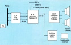
Notebook Computer An excellent application for a Class-D amplifier is a notebook computer because it has certain space restrictions and must operate efficiently to prolong its battery life (Fig. 4). The digital controller (DC '97) receives and transmits data from and to the PCI bus. It performs high-quality sample conversions for the audio codec (AC '97). The codec functions as a slave to the controller, which then performs digital-to-analog conversions, analog-to-digital conversions, analog processing such as tone and 3D stereo enhancement, and mixing.
The audio codec accepts analog input from a microphone, CD or DVD, or an external source (Line in) for mixing. It may provide external outputs for connecting headphones (with or without microphones), speakers, speakerphones, or modem connections. A Class-D amplifier can connect to the codec via an analog output (Line out).
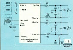
Consider the connection between the notebook computer's audio codec, a Class-D APA, and a set of speakers (Fig. 5). The input capacitors, in series with the amplifier's input resistance, form a high-pass filter.
This filter blocks any dc signal and sets the low-frequency (FLO ) -3-dB point at 20 Hz according to:
FLO = 1/(2¼RC)
Because the input signal is small, these capacitors can be small, surface-mount ceramics. Ceramic capacitors offer a smaller footprint, lower equivalent series resistance, and a longer life than do electrolytic capacitors. In an environment where high, widely varying ambient temperatures are expected, it's important that the capacitor tolerance and temperature stability be taken into account. As noted, the second-order, low-pass (LC) filter at the output sets the high-frequency corner (fHI) of the desired bandwidth, and must be designed for a specific load impedance.
In the case of a BTL load configuration, the equations used to determine the capacitance and inductance for a given load are:
CBTL = 1/(Ö—2 RL*0)
LBTL = (Ö—2 RL) / (2 *0)
where *0 = 2¼fHI is the frequency in radians per second.
The high-frequency corner should be far enough above the highest-frequency component of the Class-D APA to avoid attenuation of the audio signals, yet low enough to limit the switching losses due to the switching frequency (fS). For example, to filter fS = 250 kHz to about 1% (-40 dB) of the amplitude of the audio signal at the speaker requires an fHI of 25 kHz for a second-order filter. This is high enough to have minimal impact on the audio band. Substituting fHI into the equation for *0 yields 157 kradians/sec. For a 4-Ω load, RL = 4 Ω, LBTL = 18 µH and CBTL = 1.1 µF. Standard values of C = 1 µF and L = 18 µH can be used. Surface-mount capacitors and inductors can be used for the output, reducing the space required for the filter.
The two other capacitors in the output filter, labeled C, may be added to provide a high-frequency bypass to ground. These capacitors should be approximately 10% of 2CBTL. If the switching frequency is set close to the audio band, then a dampening resistor should be placed in series with CBTL. The choice of this resistor is based on the impedance characteristics of the speaker.
The frequency of the ramp, or triangle, generator in the APA can be adjusted by an external capacitor, COSC, over a wide range. A ceramic capacitor with stable temperature characteristics and a tight tolerance over the desired frequency range should be used because any nonlinearity introduced here will ripple through the system. Increasing fS will increase the resolution and attenuation through the output filter. However, this also will increase power losses in the transistors and filter.
The designer also must consider the control pins. Most audio power amplifiers have a shutdown pin so that the amplifier can be placed in a low-power sleep mode. This pin can be connected to the headphone jack so that the APA will be shut down and the speakers disabled when the headphone amplifier is in use. An added benefit of a Class-D amplifier is the device's ability to alert the system when a fault condition, such as under-voltage or thermal overload, is present. These pins can be monitored by the system for a fault condition, making diagnosis quick and efficient.
Be Well Grounded
When well-established layout practices are followed, a solid ground plane is as effective at reducing electrical noise on a board as a split ground plane or a star configuration. In a star configuration, one location provides a ground connection and all of the traces on the board's network are connected to it. A split ground is often found in mixed-signal systems because it's sometimes necessary to isolate the analog ground plane from the digital ground plane.
The split ground plane has inductance between both sections of the plane that dampens the noise and can cause uneven voltage potentials. However, a solid ground plane has low resistance so that when a voltage or current spike hits the ground plane, the entire plane shifts up or down. By using a solid ground plane, the overall design of the board can be simpler and will be less prone to errors in layout.
Successful use of a solid ground plane is sometimes dependent upon the architecture of the Class-D amplifier. If the device is configured in such a way that the designer can keep the input and output sections of the chip separated from each other, then the chances are reduced that high- and mid-frequency return currents will make a path to the analog input section of the chip.
The traces for the analog circuit grounds should be extremely short and connected to the ground directly underneath the chip by vias. The power circuit grounds connected to the ground plane should be placed slightly farther out from the chip and closer to the signal and power outputs. This type of arrangement uses the ground plane to separate the large current traces of the output from the input circuitry.
Next-Generation Amplifiers Class-D APAs offer many capabilities that will allow designers to advance many systems to the next generation. Improved power efficiency will extend the battery life of portable systems. Higher efficiency also means less heat dissipation, which in turn reduces the need for heat sinks and other thermal management techniques. This is particularly important for portable applications because it saves board space and allows smaller enclosures.
Because Class-D amplifiers are based on a different technology than Class-AB audio power amplifiers, a different set of design issues must be taken into consideration as Class-D devices are implemented. Just as switch-mode voltage regulators required some getting used to, designers will have to learn the requirements of Class-D amps. But, as with switch-mode regulators, the benefits far outweigh the learning curve.
About the Author
Richard Palmer
Applications Engineer
RICHARD PALMER is an applications engineer at Texas Instruments Inc. He received his BSEE front the
University of Tennessee, Knoxville.
