Defeat Serial-Interface Attenuation/Distortion with Equalization and Repeaters
Download this article in PDF format.
Transmitting high-speed data over a cable or printed-circuit-board (PCB) path will significantly attenuate and distort the signal. Transmission paths are usually transmission lines that introduce losses of 30 dB or more. Signal rounding, noise, jitter, and other distortions introduce additional problems, resulting in bit errors or the inability to recover the signal. Most serial interfaces with data rates of 10 Gb/s or more require some assistance from repeaters and equalizers.
While good signal-path design is essential, any problems can usually be corrected with the latest interface ICs that provide signal boost and adjustable equalization. The secret to achieving the best signal quality is to optimize the link’s equalization. This article looks at signal-path design and the use of contemporary serial-interface ICs to implement the best data links.
Appraising Signal Quality
The best way to judge a fast serial interface is to evaluate its bit error rate (BER). It’s usually established by the interface standard, but typically falls in the 10-10 to 10-18 range. BER testers provide the measurement, although eye diagrams on an oscilloscope also are widely used to determine the quality of an interface (Fig. 1).
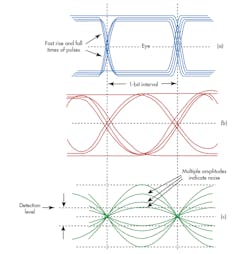
1. These eye diagrams are representative of excellent path bandwidth (a), more limited path bandwidth (b), and limited bandwidth and high attenuation with noise (c).
Fast rise and fall times produce an open “eye,” indicating good signal integrity. Attenuation and distortion over the signal path reduce signal amplitude and lengthen the rise and fall times, which in turn closes the “eye” and increases BER. Noise, jitter, and inter-symbol interference (ISI) produce other detrimental eye conditions. Today, regardless of the signal path, these issues can be resolved with available equalizers, repeaters, and retimers.
Signal-Path Design
Stripline is a pair of parallel copper traces on a PCB that implements a differential-pair transmission line, which is typical for most serial interfaces. The length may be anything from a few inches to several feet. With a constantly maintained characteristic impedance and a matching load impedance, the signal distortion and attenuation should be as low as possible without corrective methods.
Keep in mind that a transmission line acts as a low-pass filter for binary signals, thereby increasing rise and fall times and causing signal rounding and distortion as well as attenuation. These effects increase with the data rate and the length of the transmission line. Insertion attenuation due to resistive losses can be as high as 30 dB or more in some longer paths. This attenuation and distortion increase BER and produce a closed eye.
Improving Signal Quality
Signal distortion can be corrected by using an electronic method known as equalization. Equalization uses special filters to adjust the frequency response of the signal path. Figure 2 shows a signal path for a typical serial interface.
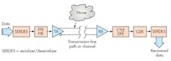
2. Here’s the complete transmit and receive signal chain for one channel with equalization.
Equalization is used at both the transmitter (TX) and the receiver (RX). The TX equalizer, called a feedforward equalizer (FFE), is essentially a high-pass filter that predistorts the signal in a way to overcome the natural effects of the channel. It boosts the signal level at the rise and fall transitions to compensate for the rounding and signal stretching.
A TX equalizer is a feedforward-equalization circuit that’s usually a DSP finite-impulse-response (FIR) filter. It provides adjustable coefficients that determine the degree of preemphasis based on estimates of the actual degree of distortion in the signal path. These coefficients can be later readjusted to optimize the signal path when the channel characteristics are known. It has been determined that too little or too much equalization can increase ISI and BER. A negotiation and optimization process produces the best results.
As for noise, the differential transmission line picks it up. However, thanks to the common-mode rejection properties of the differential pair, it’s mostly cancelled out.
Two common types of equalization used at the RX are continuous-time linear equalization (CTLE) and decision-feedback equalization (DFE). Both are used to compensate for transmission-path degradations.
The CTLE is usually a high-gain active RC filter that produces more gain at the higher frequencies to offset the losses in the path. The DFE uses a FIR filter like the FFE in a feedback path to detect the previous signal and subtract it from the incoming signal to cancel any ISI.
Linear Repeaters in SAS/SATA Applications
Most high-speed serial interfaces include some form of equalization. When attenuation over distance is a problem, repeaters are used. A good example of these repeaters are the ICs used in SAS/SATA equipment, specifically Texas Instruments’ low-power eight-channel DS125BR820 and four-channel DS125BR401A 12.5-Gb/s repeaters with equalization.
The DS125BR820 is low-power repeater/redriver that supports eight channels of high-speed data at rates up to 12.5 Gb/s. It’s applicable to interfaces such as SAS/SATA, PCIe 3.0, and Ethernet 40G-CR4 and 40G-KR4. The receivers incorporate CTLE to provide a high-frequency boost that’s programmable from 3 to 10 dB at 6 GHz. The programmability is applied via software and an SMBus or I2C interface. With this device, partners sharing the link can negotiate the transmit equalizer coefficients. The IC features ac-coupled CML inputs and outputs, and power consumption of 70 mW per channel.
A related product is the DS125BR401A, a four-channel repeater/retimer that handles speeds to 12.5 Gb/s. It too uses continuous time linear equalizers. The equalization is programmable over a 3- to 10-dB range with a linear output driver. Programmable settings are applied via an SMBus or I2C interface, or loaded by way of an EEPROM. Configuration information is automatically loaded on power up, eliminating the need for a support microcontroller. Evaluation modules are available for both products.
Green-Box Testing: Optimizing High-Speed Serial Links
As indicated earlier, the key to producing the best signal in a serial interface is to optimize the transmitter equalization settings. A special procedure for doing this is called green-box (GB) testing. Its objective is to determine the optimum by sweeping the essential parameters and measuring the result to produce a figure-of-merit (FoM) output for comparison. GB testing is a good way to deal with systems with a large channel count, and is becoming a standard method for ensuring that systems meet the best BER.
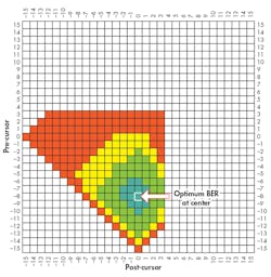
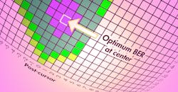
3. Shown is a representative green-box test plot, which is a graphical representation of BER for each pair of TX coefficient settings.
When designing a system, you typically do not know the characteristics of the signal paths involved. Therefore, initial TX FIR coefficients are going to be a guess. But that’s okay, because the GB test starts with these coefficients and then sweeps them over a range, making measurements that identify a pattern indicating when a channel has been optimized. This pattern is shown as a graphic that shows the BER for each pair of TX coefficient settings. Figure 3 depicts a common GB plot: the green areas indicate no errors; the yellow areas indicate some errors; and the red errors indicate maximum errors.
The transmitter is the device under test (DUT) in a GB test. It’s connected to a pseudorandom-bit-sequence (PRBS) generator that sends a protocol-appropriate bit chain. The initial coefficients establish pre-cursor and post-cursor values. The bit pattern is sent and the receiver equalizer adjusts; then the BER at the receiver is measured. This output is subsequently compared to the desired BER for the system and the result is plotted. The best coefficient settings are indicated at the center of the green region.
The TI devices described above were tested in an external miniSAS-HD environment using a DS125BR820EVM TI evaluation module. The test results demonstrate how linear equalization can improve system margin and allow for the extended channel configurations that are required in the latest storage systems.
About the Author

Lou Frenzel
Technical Contributing Editor
Lou Frenzel is a Contributing Technology Editor for Electronic Design Magazine where he writes articles and the blog Communique and other online material on the wireless, networking, and communications sectors. Lou interviews executives and engineers, attends conferences, and researches multiple areas. Lou has been writing in some capacity for ED since 2000.
Lou has 25+ years experience in the electronics industry as an engineer and manager. He has held VP level positions with Heathkit, McGraw Hill, and has 9 years of college teaching experience. Lou holds a bachelor’s degree from the University of Houston and a master’s degree from the University of Maryland. He is author of 28 books on computer and electronic subjects and lives in Bulverde, TX with his wife Joan. His website is www.loufrenzel.com.
Comment About the Article
To join the conversation, and become an exclusive member of Electronic Design, create an account today!

Leaders relevant to this article: