Mount a Photodiode to Maximize Speed (.PDF Download)

Direct coupling is advantageous in many photodetector applications, such as viewing laser thresholds and modulation depth. I patented a very fast photodetector mount1,2 in the early 1970s using these same criteria. The patent is long expired, so the method is in the public domain.
Criteria
The main points of this design are to place the photodiode in series with the load and a reverse bias potential (Fig. 1), while keeping all extraneous leads as short as possible to keep any parasitic reactance to an absolute minimum. Parasitic reactance in the high-frequency signal path slows the response and/or causes undesirable ringing at the oscilloscope.

1. Photodiode and reverse bias supply in series with load.
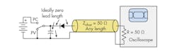
The load is a 50-Ω termination at the oscilloscope brought to the photodiode by a length of coaxial cable of the same characteristic impedance (Fig. 2). By the magic of transmission lines, the photodiode end of the coaxial cable appears as a 50-Ω resistor, so the task is to assemble a series combination of the photodiode, the end of the coaxial cable, and the bias potential with close to zero lead lengths. Insertion of bias away from the photodiode scatters some of the signal in each direction and distorts the response. Insertion of bias at the end of the coaxial transmission line at the photodiode largely eliminates this problem!

2. Transmission line terminated in its characteristic impedance.
Figure 3 shows the complete circuit for normal high-speed PIN photodiodes and avalanche photodiodes. The capacitor provides a short path for the high-frequency signal components, so the bias supply needn’t be small or nearby. Note that each component in the loop encompassing the end of the coaxial cable, the bias capacitor, and the photodiode must have the shortest possible lead lengths. Strive for zero length.
3. Circuit of fast photodetector.
For applications that don’t require high-speed photoconductive (photoamperic3) operation, the switch disables the bias supply and shorts to ground to provide a dc path for operation in photovoltaic (PV) mode. PV mode is slower, quieter, and operates well into a higher load resistance for greater sensitivity at the expense of speed.
