Download this article in PDF format.
Direct coupling is advantageous in many photodetector applications, such as viewing laser thresholds and modulation depth. I patented a very fast photodetector mount1,2 in the early 1970s using these same criteria. The patent is long expired, so the method is in the public domain.
Criteria
The main points of this design are to place the photodiode in series with the load and a reverse bias potential (Fig. 1), while keeping all extraneous leads as short as possible to keep any parasitic reactance to an absolute minimum. Parasitic reactance in the high-frequency signal path slows the response and/or causes undesirable ringing at the oscilloscope.
1. Photodiode and reverse bias supply in series with load.
The load is a 50-Ω termination at the oscilloscope brought to the photodiode by a length of coaxial cable of the same characteristic impedance (Fig. 2). By the magic of transmission lines, the photodiode end of the coaxial cable appears as a 50-Ω resistor, so the task is to assemble a series combination of the photodiode, the end of the coaxial cable, and the bias potential with close to zero lead lengths. Insertion of bias away from the photodiode scatters some of the signal in each direction and distorts the response. Insertion of bias at the end of the coaxial transmission line at the photodiode largely eliminates this problem!
2. Transmission line terminated in its characteristic impedance.
Figure 3 shows the complete circuit for normal high-speed PIN photodiodes and avalanche photodiodes. The capacitor provides a short path for the high-frequency signal components, so the bias supply needn’t be small or nearby. Note that each component in the loop encompassing the end of the coaxial cable, the bias capacitor, and the photodiode must have the shortest possible lead lengths. Strive for zero length.
3. Circuit of fast photodetector.
For applications that don’t require high-speed photoconductive (photoamperic3) operation, the switch disables the bias supply and shorts to ground to provide a dc path for operation in photovoltaic (PV) mode. PV mode is slower, quieter, and operates well into a higher load resistance for greater sensitivity at the expense of speed.
The really fast design in the references requires a photodetector chip with bond leads to the end of a transmission line and a very low inductance parallel plate capacitor to provide bias insertion. This design is a compromise suitable with photodiodes in small semiconductor packages with leads. More ringing results, but it will only be observable with a really fast oscilloscope.
Construction
The following series of photographs shows the steps I performed in assembling such a detector. Start with a few inches of coaxial cable. I used RG-174/U because it’s small, flexible, and available. RG-188 would be better, because the Teflon dielectric will not melt at soldering heat. Expose the center conductor at both ends. At the photodiode end, remove the shield very close to the end of the dielectric.
Next, mount a physically small capacitor to the end of the shield (Fig. 4). Select a capacitor with good high-frequency characteristics and adequate working voltage for the desired bias potential. This is a low-voltage InGaAs PIN photodiode4 with a low operating voltage, so I used an ordinary 0.1-μF, 50-V bypass capacitor. Consider using a chip capacitor for even lower inductance.
4. Mount a physically small capacitor to the end of the shield.
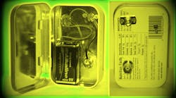
Before assembling the cable to the photodiode, lay out the parts in whatever case you will use, drill the holes, and make sure everything fits. I strongly urge the use of metal enclosures to provide shielding against interfering signals. The case needn’t be expensive—this example uses an Altoids tin, a hobbyist favorite.
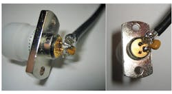
You may want to mount the essential components into the case before attaching the coaxial cable and capacitor to the photodiode. I got lucky, and the assembly fit through the hole after I made the critical connections in Figure 5. Trim another millimeter or two from the total path length if you can. This is a 1.5-GHz photodiode capable of 0.2-ns rise and fall times that still shows ringing on a fast oscilloscope.
5. Attach coax and capacitor to the photodiode after mounting essential components into the case.
Attachment of the other end of the coaxial cable to the BNC connector is similarly adequate for moderate speed. For a faster photodiode, use an SMA bulkhead jack connector that properly terminates the coaxial cable rather than one with a solder-pot terminal. This construction works well for photodiodes with 0.5- to 1-ns rise/fall times or for faster photodiodes that you will observe on an oscilloscope with less than 500-MHz bandwidth. For the ultimate performance, see the first two references.
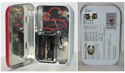
Figure 6 shows the resulting instrument. Construction, done with available parts, is inexpensive. You will probably have to purchase only the photodiode.
6. The resulting instrument.
Photodiodes vary in their construction and packaging. One side will have more stray capacitance than the other if it’s connected to the case. If so, apply bias to that side and take the output signal from the other. Let the package determine bias and output polarity.
Optional Reverse Termination
This arrangement is near optimal for most photodiodes. The speed of response for a few photodiodes is RC-limited rather than transit-time-limited. Those devices may work twice as fast into 25 Ω as into 50 Ω. I remember a Hamamatsu avalanche photodiode that behaved that way about 35 years ago. In that case, consider adding a 50-Ω chip resistor directly across the coaxial cable at the photodiode end to halve the RC product.
7. Circuit of fast photodetector with reverse termination.
Such a reverse-termination resistor also absorbs any reflections that return down the coaxial cable from an imperfect termination at the oscilloscope. You can even omit the 50-Ω termination at the oscilloscope if you incorporate the reverse termination (Fig. 7).
Conclusion
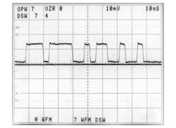
Simple construction results in a high-speed photodetector with very good performance suitable for laboratory use. Figure 8 shows the response of this unit on a 400-MHz oscilloscope. The center line is the zero signal reference.
8. Mounted photodetector response.
Note that photodiodes with built-in preamplifiers have greatly improved sensitivity, but almost always tolerate only a capacitively coupled load. They generally can’t drive a low-impedance load and always have a dc offset potential at the output. This last reference shows ways to direct-couple such amplified photodiodes to improve their usefulness as laboratory monitors.5
Sam Green retired in 2011 as a technical fellow after 42 years with McDonnell Douglas/Boeing. Sam has undergraduate and graduate degrees in Electronic Engineering from Northwestern University and the University of Illinois at Urbana respectively. Sam specialized in optical data communications and photonics. Sam is a life-senior-member of IEEE, a Registered Professional Engineer in Missouri, and an extra class radio amateur. Sam has dozens of publications and holds eighteen patents. Contact Sam at [email protected].
References
1. View US Patent number 4,103,157 at http://patft.uspto.gov/netahtml/PTO/srchnum.htm.
2. “50 picosecond detector laser pulse monitor,” S.I. Green, Review of Scientific Instruments, Vol. 47, p. 1083, 9/1976.
3. “Photodiode operating mode nomenclature,” Geist, Jon C., Applied Optics, vol. 25, p. 2033.
4. Lasermate model RFC-M13A306 http://www.lasermate.com/ReInGaAs.html.
5. “Direct coupling of high-speed optical detector preamplifiers,” S.I. Green, Review of Scientific Instruments, Vol. 71, p. 3918, 10/2000.


