Why the fresh emphasis on low-noise amplification?
Some of it is an issue of signal-to-noise ratio (SNR). Today, sensor voltages and device operating voltages are lower than they used to be, so noise is larger in relation to signal levels. Another factor is that the data converters being used have higher resolutions than in the past, so they need cleaner inputs.
What kind of noise are we talking about?
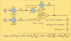
This noise is intrinsic to the amplifier or generated by associated passive components and then amplified. External noise is a system-level issue.What are the sources of this noise? Johnson (thermal) noise is generated by input and feedback resistors (en,R2) and the amplifier’s intrinsic voltage noise (en) and current noise (in) (Fig. 1).
The equation for noise referred to in the circuit input (NoiseRTI) in Figure 1 shows the contributions of all the noise sources. The “k” factor in the expression’s resistor noise is Boltzman’s constant. T is absolute temperature (Kelvin), and R is resistance in ohms. As a rule of thumb, a 1-kO resistor generates a noise of 4 nV/vHz at room temperature higher than some modern op amps.
How is noise expressed?
To allow all noise sources to be combined in a simple square root of the sum of the square’s expression, baseband noise specs are given in terms of nV (or pA)/vHz. That’s possible as long as the noise sources are uncorrelated so the probability of any given amplitude across the frequency spectrum follows a normal (Gaussian) distribution.
Noise isn’t really constant across all frequencies, is it?
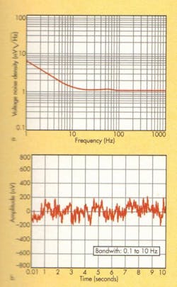
No. Both en and in have two components (Fig. 2a): low-frequency “1/f” noise, whose spectral density increases at 3 dB/ octave as frequency decreases, and spectrally flat “white” noise at higher frequencies. For applications where 1/f noise is most critical, data sheets may also show the peak-to-peak noise across a limited bandwidth, e.g., 0.1 to 10 Hz (Fig. 2b).
What is the “corner frequency,” and why is it important?
The frequency at which the 1/f noise spectral density equals the white noise is known as the 1/f corner frequency (FC). It is obtained by extending the 1/f and white-noise portions of the noise plot and noting the point at which the lines cross. It is important as a figure of merit. Also, the 1/f corner frequency isn’t necessarily the same for voltage and current noise.
Yet it often is only specified for voltage noise.How can I use this information in choosing a low-noise amplifier?
Consider the frequency band of interest and relate the rms noise within that bandwidth to your system requirements. Because noise is specified in terms of the square root of frequency, the various noise contributions can be evaluated as the square root of the sum of their squares. Thus, the total rms voltage noise, en,rms, in the bandwidth FL to FH, is simply:
where enw is the broadband white noise, FC is the 1/f corner frequency, and FL and FH define the measurement bandwidth of interest.
Generally, any noise component that is four or five times higher than any of the others becomes dominant, and the rest can be disregarded. So at higher frequencies, FC ln(FH/FL) becomes insignificant, and the total rms noise is simply the white noise times the square root of the frequency difference. In fact, if FH is very much higher than FL, the total rms noise is simply the white noise times the square root of FH.
On the other hand, when you’re operating in the 1/f region, the total rms noise is the noise level at the corner frequency (i.e., the white noise level) times the square root of the corner frequency times ln(FH/FL).
What about current noise? The fourth and fifth terms in the equation in Figure 1 show that when current noise flows through an impedance, it generates a noise voltage that adds to the other noise voltages in the square root of the sum of the squares. Also, while voltage noise is the first spec designers look at, if circuit impedance levels are above en/in (sometimes called the amplifier’s “characteristic noise resistance”), current noise dominates.


