Optical Fiber Powers MRI-Compatible Cardiac Catheter
Optical fibers are very good for conveying data, but generally impractical for transferring useful amounts of power. Nonetheless, a joint team from Royal Philips NV (Eindhoven, Netherlands) and Erasmus Medical Center (Rotterdam, Netherlands) and Rasmussen Medical Center (Rotterdam, Netherlands) developed a benchtop-prototype cardiac catheter that uses multiple optical fibers to deliver power to a cardiac catheter.
This novel approach, explained in the lengthy, detailed paper “Electrifying catheters with light,” from the Optical Society of America, targets eliminating two problems associated with a catheter’s wire leads when the patient is being assessed with an MRI machine: localized heating due to wires resonating with the magnetic field (a rise of more than 70°C within 30 seconds), and image degradation due to metallic wire interference. As an added benefit, an optical link also provides galvanic isolation.
The proof-of-concept design (Fig. 1) presently uses three optical fibers plus a wire pair; the next planned phase will try to eliminate those remaining wires. One fiber carries a higher-power light which will convert to a high voltage (about 44 V) for eventual use by the scanner’s transducer. The second carries power for use at the lower voltage for the ASIC and electronics mounted at the catheter tip. The third sends the transducer data back to the console, after encoding by the ASIC (which also controls pulsing of the transducer).
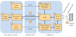
1. This block diagram of the optoelectrical ultrasound imaging system shows electrical connections as solid arrows and the optical connections as dashed arrows. (Source: Optical Society of America)
The bidirectional ultrasonic unit is a capacitive micro-machined ultrasonic transducer (CMUT) array consisting of 512 active cells, each with a diameter of 60 µm; total active area is 2 × 1 mm2. The CMUT echo output is digitized via a 14-bit analog-to-digital converter (ADC) with a 5-ns sampling time, ramp-compensated for tissue-distance attenuation via a time-gain compensation (TGC) amplifier (a standard technique), then averaged over 16 samples before being encoded by the ASIC.
Dual Subsystems
The two optical-power subsystems are very different and tailored to their load requirements. For the CMUT-power path, a high-power violet laser diode’s output is coupled through a 1-mm diameter glass fiber to a 50-V LED comprised of 18 monolithic LEDs in series. A capacitor stores energy so that about 2.5 μJ will be available for the pulsing of the transducer array. A 16-kHz charge pump and inverter takes the 44-V output of the LED array and boosts it to –90 V needed by the transducer. The high-voltage laser receives 1.4 W of power; power efficiency from source to output of the optical/electrical conversion circuitry at the catheter tip is 13.4%.
The low-voltage subsystem powers the electronics and provides bias voltage to the VCSEL , which sources the optical signal needed for transmission of data back to the console. This path is powered by a 405-nm laser from a Blu-ray disk player, and is coupled via a lens and dichroic mirror into a 400-µm diameter glass fiber.
The receiving end doesn’t use a conventional photodiode. Instead, it uses a blue LED in “reverse mode” to convert light into electrical power, which is then regulated by a 1.8-V shunt device. (The GaN blue LED is used as a photovoltaic convertor because its high bandgap of 2.8 eV provides a compact power source that can deliver directly up to 2.4 V.) Electrical power to the low-voltage laser is 595 mW, and end-to-end conversion efficiency is 36.8%.
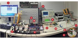
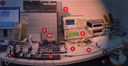
2. The labeled numbers in this photograph of the optoelectrical ultrasound imaging system match the items shown in the block diagram. (Source: Optical Society of America)
The data-transfer laser operates at 850 nm, using amplitude modulation to transmit data from the CMUT, which has been encoded by the ASIC. The received optical signal is focused on a photodiode, and then goes to a 20-dB amplifier for subsequent demodulation and decoding.
Although this catheter (Fig. 2) isn’t completely “wireless” and still requires a pair of wires to send control signals to the ASIC at the catheter tip, it represents a major step toward an all-optical design. The long-term goal is to use just a single laser source, and a single fiber. A laser source and fiber could be replaced by a beam splitter at the catheter tip, with the same fiber used as a return path using a dichroic mirror at both ends. The control signals would also be sent over that optical fiber, with some receiving logic integrated in the catheter tip.
Of course, space is extremely limited: the maximum available diameter at the catheter tip, which must house electronics, CMUT, electrooptical elements, mirror, and lenses, is just 3 mm.

About the Author

Bill Schweber
Contributing Editor
Bill Schweber is an electronics engineer who has written three textbooks on electronic communications systems, as well as hundreds of technical articles, opinion columns, and product features. In past roles, he worked as a technical website manager for multiple topic-specific sites for EE Times, as well as both the Executive Editor and Analog Editor at EDN.
At Analog Devices Inc., Bill was in marketing communications (public relations). As a result, he has been on both sides of the technical PR function, presenting company products, stories, and messages to the media and also as the recipient of these.
Prior to the MarCom role at Analog, Bill was associate editor of their respected technical journal and worked in their product marketing and applications engineering groups. Before those roles, he was at Instron Corp., doing hands-on analog- and power-circuit design and systems integration for materials-testing machine controls.
Bill has an MSEE (Univ. of Mass) and BSEE (Columbia Univ.), is a Registered Professional Engineer, and holds an Advanced Class amateur radio license. He has also planned, written, and presented online courses on a variety of engineering topics, including MOSFET basics, ADC selection, and driving LEDs.
Comment About the Article
To join the conversation, and become an exclusive member of Electronic Design, create an account today!

Leaders relevant to this article: