Relay-Based ON/OFF Flip-Flop Remembers State During Power Failure (.PDF Download)
Many varieties of ON/OFF control circuits use some form of flip-flop that responds to a pushbutton switch or other control input. These all have volatile memory and default to an OFF condition if power is turned off, and sometimes that's even the preferred situation. However, if your application must remember what it was doing when power failed and resume from where it left off when power is restored, you may have a problem.
Here's a flip-flop circuit that remembers its state indefinitely when power is off. Furthermore, the circuit consumes no power at all, except for a brief instant when triggered from one state to the other. Thus, it’s well-suited to battery power; a couple of lithium coin cells can provide years of battery life.
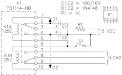
In the design (Fig. 1), K1 is a 5-V dc, dual-coil magnetic latching relay with DPDT contacts. If you search the various distributor offerings, there are about 70 different models of this type relay at coil voltages from 4.5 to 24 V dc, made by four manufacturers, and costing between $3 and $8 in single quantities. They are well built, sealed, very small, and typically have contacts rated for 2 A at up to 250 V ac.
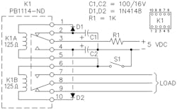
1. This two-coil relay configuration provides a latching flip-flop action without active electronics and retains its state even after power is removed. Component values are not critical.
One set of contacts (pins 2, 3, and 4) are used to steer the flip-flop, and the other set (7, 8, and 9) are available for the end application. In the state shown, C1 has charged to 5 V through R1. Closing S1 discharges C1 through D1 to pulse the K1A coil, transferring the contacts. Then C2 charges through R1 to await the next closure of S1, which discharges C2 through D2 to pulse the K1B coil, returning the contacts to the original state.
