What Do Clocks, Carriers, Local Oscillators, and FM Have in Common? (.PDF Download)

The master timing control circuit for most electronic applications is a precision signal source. For digital applications, it’s an accurate clock. In RF applications, it’s a carrier source for a transmitter or a local oscillator (LO) for a receiver. And if frequency modulation (FM) is involved, a modulator and demodulator are needed along with a carrier source.
In all of these cases, a phase-locked-loop (PLL) frequency synthesizer is an excellent choice. It provides not only the precision and accuracy needed, but also a flexible way to change frequency.
PLL 101
Just as a review, a PLL synthesizer is a closed-loop controller with feedback (Fig. 1). A voltage-controlled oscillator (VCO) generates the output signal. Frequency is determined by an LC resonant network, but controlled by a dc input voltage derived from a phase detector and a low-pass loop filter.
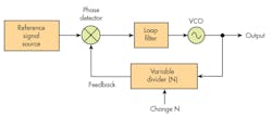
1. The basic configuration of a PLL features a VCO output, controlling circuits such as the phase detector, and feedback dividers.
The input to the phase detector is usually a stable reference signal from a crystal oscillator. The second input to the phase detector is a signal derived from the VCO output that’s usually divided down by a variable-frequency divider. The two inputs to the phase detector must be the same frequency.
