What’s All This LM334 Stuff, Anyhow? (.PDF Download)
Over 10 years ago, Bob Pease did a nice video about current sources:
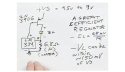
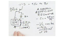
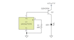
He described a circuit that used an LM334 current-source chip as the basis for an LED driver (Fig. 1). It’s a neat circuit, where the LM334 power pin draws from the base of a PNP transistor. This servos the current until the LM334 senses 0.068 V on its “R” pin. By putting in a 6.8-Ω resistor, Pease caused the current through the LED to be 10 mA.
1. Bob Pease used an LM334 current source to servo the current from a PNP transistor through an LED diode. The LM334 will draw current into its V+ pin until the voltage on the R pin reaches 0.068 V. With a 6.8-Ω resistor, the current will be 10 mA through the LED, and one-hundredth of that into V+. (Courtesy of Andy Aronson, Texas Instruments)
To my dismay, a person left a comment on the video, “Schematic at 09:07 is wrong by far. Collector branch should be disconnected from the sensing resistor of LM334, and connected (through the LOAD) directly to Ground." Anyone who calls Bob Pease "wrong by far" needs to be on pretty solid ground. I think this person does not understand the nature of the circuit.
Perhaps the commenter saw this YouTube video that is wired the same way:
That circuit is sub-optimal as well. If you hook it up this way (Fig. 2), you are depending on the beta (current gain) of the PNP transistor to set the current in the LED. Different transistors of the same part number can have wildly different beta values.
2. A commenter on YouTube said Pease was “wrong by far” and that the circuit should be connected this way. Unfortunately, the current in this circuit depends on the beta, or current gain, of the transistor.


