What’s All This Varactor-Input Amplifier Stuff, Anyway?
This file type includes high-resolution graphics and schematics when applicable.
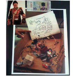
In 2008, Marcello Salvatierra took the picture above of a circuit Bob Pease had just built. Bob told him it was based on a circuit that Jim Williams did in 1967. Despite working for competitors, Bob and Jim were good friends.
I did not recognize it, so I asked some analog aficionados what it might be. Alan Martin redrew the circuit in Altium, which made its signal paths clearer. Bob Dobkin, CTO of Linear Technology, recognized it immediately. He said, “At a glance, it looks like a varactor input op amp, like the Philbrick P-2”. This makes sense; Pease wrote a chapter about the P2 in Jim Williams’ analog design book.
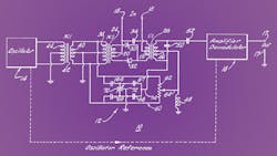
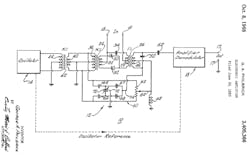
This revealed that the V47 diodes were not the dual Vishay diode, but rather the American MicroSemiconductor varactor diode. The varactor-input amplifier was invented by Bob Pease’s boss George Philbrick in 1965, and patented in 1968 (Fig. 2). Lewis R. Smith did a patent in 1969 for Analog Devices. Jim Williams worked for MIT, and both ADI and Philbrick were connected to MIT. I have to believe that they all shared or learned of the varactor input via MIT.
A varactor bridge input lowers the input bias current below a picoampere. The input diode bridge, excited by an oscillator coil, converts a dc input voltage to an ac voltage. Then you feed the signal into an ac amplifier, and after that demodulate the ac output to make an amplified dc signal.
The internal ac coupling means that the 1/f noise is greatly reduced, as in a chopper amplifier. If you use a high-voltage input capacitor and transformer, the common-mode voltage can be hundreds of volts. The cleverness of Pease’s circuit is that the single transistor makes the oscillation, and also does the amplification. Since the input is in phase to the oscillation, the demodulation is in phase, so you can use a capacitor to integrate out the ac and turn it back into dc. One transistor doing three functions was pretty neat in 1967 when a transistor cost hundreds of today’s dollars. Pease noted the Philbrick P2 amplifier cost about half of what a VW Bug did in 1970.
I re-drew Alan Martin’s Altium schematic in my old OrCAD 9 (Fig. 3). That is the great thing about CAD, it lets you push and shove things around so that the schematic looks good.
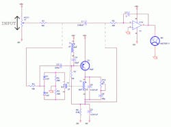
Alan Martin proposed that the dotted lines to the PNP circuit meant you were supposed to replace capacitor C1 with the PNP circuit, and I agree. If Pease wanted the cap and the PNP circuit in parallel, he would have used solid lines.
While the circuit resembles a transformer-coupled blocking oscillator, it is actually a tank oscillator. Rather than the base capacitor and inductance setting the frequency as in a blocking amplifier, the frequency of Pease’s circuit is set by the LC time-constant of the L1 inductor and parallel C5 capacitor in the transistor’s collector circuit. The tiny 32-pF C4 capacitor sends this frequency back into the base of the transistor, and regenerates the oscillations. Coil L3 excites the varactor bridge.
While it would horrify Pease, I did Spice simulations. The simulations were instructive, but not satisfying. Remember, computer simulations are not a proof; they are just a re-statement of the hypothesis. Pease left no record of the oscillator frequency, but the various pF value capacitors made me suspect it would work at a megahertz. I started with a transistor with an fT minimum of 50 MHz and then switched to a RF PNP transistor with a 5-GHz fT. The varactors are 47 pF nominal. If you build this, remember a 12-pF scope probe is likely to ruin the intended circuit operation. A FET probe would be better.
The horrid thing about this circuit is that everything interacts. If the voltage on varistor transformer tap L3 gets over 1.2 V, then it forward-biases the varactor diodes and loads the whole transformer. The base drive coil also affects the other coils. It will take energy out of the system and kill the oscillation if it is too large, and won’t sustain oscillation if it is too small.
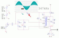
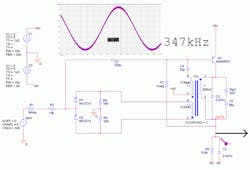
Transformer inductance ratio is the square of the turns ratio. A 1:3 turns ratio means an induction ratio of 1:9. I was able to get the L1:L2 inductance ratio (60T:4T ~ 225L:1L). I had to bump up the L3 inductance to get a good excitation signal close to ±800 mV. I got the best results at 350 kHz, although Spice is happy to simulate a 5-MHz oscillator when you use a 1-µH L1 winding.
My design procedure was to reduce the 220-pF input capacitance so that I could see the varactor front end working, and then pick an L1 inductance to set an operating frequency. After that, I set L2 as 1/225 the value, and did Spice runs adjusting Rpt1 until it is as large as possible while sustaining oscillations. It is critical to introduce this damping, so that the input from the varactor bridge will have an effect. If the tank is driving hard against the rails, the addition of the varactor input pulses will have no effect. The circuit will oscillate, but it won’t amplify.
Once the circuit oscillates, you can adjust the varactor excitation coil L3 to get somewhere just under ±1 V. You may have to tweak the Rpt1 value back down to keep the whole mess oscillating. Once you have this tuned in, you get the satisfaction of seeing the neat waveform created by the varactor front end (Fig. 4). Note: C2 is 0.0022 pF, to remove the base coupling. The waveform is the “design intent” of the varactor bridge output.
All of the usual Spice misery ensued. You have to make the minimum time step down around 10 ns, and be sure to do at least one run out to 30 or 40 ms, since the initial energy of the turn-on can dissipate and the oscillator will drop down to a lower amplitude. Just as frustrating, the input voltage can kill the oscillation once you make C2’s value 220 pF.
Pease talks about the old P2 amp going “into mode,” in which the input bridge helps regenerate the oscillations. I could never get that to happen, and I might be way off base with the frequencies I am using. I also am not modeling leakage inductance; I kept the transformer coupling coefficient at 1. I was lucky if I could get a gain of 9 from the input to the output (Fig. 5).
The modest gain might be why Pease put an integrator after this stage. He could tweak R7 to get the output close to zero, and then adjust the input pot to get the output at zero. Then he could swing the pot through its range as he watched the meter slew up and down.
Bob’s good friend Marcello told me Pease was extremely proud of this circuit and I see why. I have to believe Pease started with a transformer and designed the components around them. I kept those component values in my Spice schematic, but I could not get the circuit to perform as smoothly as I wanted. Perhaps I should be delighted at the gain of 9. Maybe I needed to boost the oscillator frequency even higher. Simulating magnetics is always a challenge.
Pease made “Jim’s analog computer” by using “Jim’s special op amp” in an analog computer circuit. Pease loved analog computers. Any thoughts on this circuit are welcome.

About the Author

Paul Rako
Creative Director
Paul Rako is a creative director for Rako Studios. After attending GMI (now Kettering University) and the University of Michigan, he worked as an auto engineer in Detroit. He moved to Silicon Valley to start an engineering consulting company. After his share of startups and contract work, he became an apps engineer at National Semiconductor and a marketing maven at Analog Devices and Atmel. He also had a five-year stint at EDN magazine on the analog beat. His interests include politics, philosophy, motorcycles, and making music and videos. He has six Harley Sportsters, a studio full of musical instruments, a complete laboratory, and a video set at Tranquility Base, his home office in Sun City Center Florida.
Comment About the Article
To join the conversation, and become an exclusive member of Electronic Design, create an account today!

Leaders relevant to this article: