What's All This Fuzzy Logic Stuff, Anyhow? (Part IV)

This is the fourth in a six part series.
Recently, one of my far-flung friends sent me a magazine article, along with his puzzled comment: "Can Fuzzy Logic REALLY do THIS—and nobody else can do it?" I read the story. It explained that in Europe, there was a requirement for a speed limiter for heavy trucks, at 53.4 mph (86 km/hr). The article claimed that such a speed limiter couldn't be done by any conventional controller.
This was partly because it was very hard to design a model for a truck. There were so many different kinds and versions and manufacturers of trucks. Plus, there were heavy trucks and lightly loaded modes of operation. The truck model would have to work on upgrades and downgrades. Also, the task was claimed to be very nonlinear. So, the author proposed using Fuzzy Logic (FL) to accomplish this. Because his controller would be very versatile and very robust, it wouldn't need to be programmed differently for different types of trucks.
Now, if this article said there were something that I couldn't do with op amps, resistors, and capacitors, then that would present kind of a serious challenge, eh? I always like challenges.
I thought about this. A truck tends to accelerate over a wide range of speeds. It picks up speed, faster or slower, according to its load, proportional to its accelerator-pedal setting, and based on how the engine's torque is geared to the load and influenced by the grade of the road. That sounds like an integrator—an integrator with a larger or smaller feedback capacitor (to represent how the mass of the truck changes), with a positive bias (in case it's "on a downgrade"), or with a negative bias (in case it's "on an upgrade").
A truck's model sounds pretty easy to me—an integrator with some biases, varying gains, and a little lag in the control path. I could then use the model to drive an analog controller like the one shown in Figure 1. Now, I concede that it would be hard to model a truck for every situation, at all speeds. But in this case, a model that's fairly realistic at around 45 to 55 mph is easy to design.
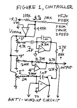
Figure 1. A Possible Analog Controller
See Figure 2—an integrator with a controller input (with a little lag). What's so difficult about that?
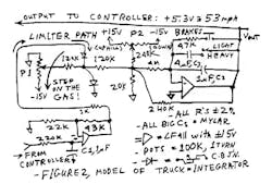
Figure 2. Model of Truck-Integrator
So I sat down with a big sheet of paper, added a few control elements to a simple PID loop, proposed some nominal component values, and drew up a couple of wires to connect this to the model of the truck (Fig. 1, again). This is very much like the controller for my "Ball-On-Beam Balancer" (Electronic Design analog supplement, Nov. 20, 1995, p. 50).
Next, I started to draw up some waveforms to show how it would work. In my book,1 I call this a "choreography" to illustrate how each waveform relates to one another. I convinced myself that this loop could be stable and wouldn't oscillate. This is largely related to the way that a control loop can be fairly SIMPLE, NIMBLE, and quick to increase or decrease gas-pedal settings. The truck can accelerate at about 0.01 to 0.05 G's if it's heavily loaded, or perhaps at five or 10 times that rate if it's empty. ANY driver can easily pull his foot off the gas pedal when he wants to avoid exceeding a speed limit—if he wants to, and if he remembers to. Even an FL controller can do that. Even a PID controller can do that. Controlling the speed of a vehicle isn't too difficult. Anybody can do it.
That's because a truck trying to accelerate with a nominal amount of power, driving a wide-range load, is only an integrator, just like an op amp. Everybody likes op amps because it's easy to close a loop around them—whether at high gain, or at low gain—because the phase-shift of an integrator is 90°. Therefore, the loop will be stable. But then I saw the flaw in my first-draft controller circuit: The PID controller has probably been trying to accelerate at full power for a long time, because the vehicle's speed is below the limit. The integrator has, thus, been fed a large dc error signal for a long time—and its output would be near the negative limit! That could easily cause overshoot, and the loop couldn't help it. Overshoot would occur, even though stable operation would eventually take over.
How can I avoid this overshoot? After all, in a speed limiter, overshoot is a really bad kind of performance. The requirement for this limiter is pretty strict, allowing only a small amount of overshoot (about 3 mph max).
Then I remembered some notes by Dave St. Clair2 about "wind-up." Any PID controller can have its integrator term go off to a limit when you don't want it to, such as when the loop isn't in control for a long time. That's called wind-up. How do we avoid this? After all, any PID controller tends to exhibit this wind-up, if it's tasked to pull a large inertial MASS up to a new level. This is NOT a new or unique task. Actually, some PID controllers do very well at this!
I recalled that the remedy is termed "anti-wind-up." I tried looking this up in several books. I found it really hard to find any further mention of wind-up, or of how to perform anti-wind-up. Still, I figured out that it isn't rocket science! This is a special case of analog computation—with a bit of hybrid/digital control.
Then I remembered seeing some sketches that had the same shape (Fig. 3) as my crude first-hack PID controller with wind-up. In the old book by MacNeill and Freiberger, Fuzzy Logic,3 about the origins of FL in control loops, there was that sketch on page 115 showing the performance of a little boiler. McNeill said that the "conventional controller" would cause overshoot, whereas an FL controller, designed by Mr. Mamdani, seemed to avoid overshoot. Ahem! I realized that this was an example where a PID controller was said to give poor performance—because it was MIS-applied. It had a big overshoot, a result of its integrator term having a lot of wind-up. If I were foolish enough to disregard wind-up, then my controller would show bad overshoot too!
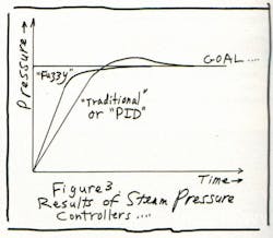
Figure 3. Limiting Overshoot in the System Step Response
Why didn't Mamdani's FL controller have a lot of wind-up? Aha—it didn't have any integrator term. Then why did it slow down and converge on the right answer without overshoot? It was easy to see that was due to the FL controller cutting its gain back severely, as it approached the null—because it ran out of gain.
The example showed that the FL controller's response seemed to be very nice, well-behaved, and slow as it approached the target. But the book didn't show how that controller would react when a load was placed on the boiler to draw off steam, so that it could do some useful WORK. I could see what was going on: the FL system didn't have much gain, and it would look good only if you didn't put on a load. The FL controller had P and D terms, but it didn't have any integrator to provide high gain against a dc load.
The FL engineers praised one good feature of their controller—the startup—in comparison to a MIS-applied conventional (PID) controller. Yet, they avoided mentioning the situation where their FL controller would show its deficiency. It would bog down and allow the boiler pressure to drop by 10% or more when the boiler had to do some work.
Any good PID controller would NOT let the boiler pressure drop under a load. Instead, after a brief transient drop of pressure, the PID would pull the pressure right back to the ideal pressure, with no dc errors. If properly applied with anti-wind-up, therefore, the PID controller could easily perform well at startup, without overshoot, and with good regulation against loads. Have you ever seen any FL controllers that were able to do that?
Now, after learning about this problem, could I design a controller for a truck's speed limiter? Sure. Could I invent a decent anti-wind-up circuit? Certainly (Fig. 4). The detector can tell if the controller's error is far from null, and it applies a RESET switch across the integrator. The integrator is reset to zero output, until the controller begins to take effect, and then the integrator in the controller begins to servo out the dc error. Of course, this circuit is much more complicated and more versatile than I would really require. But, I wanted to conduct some experiments.
Do I have confidence that this controller will work well, and won't overshoot? I definitely do. I don't know how the FL controller was designed, and I don't know what features it has. I don't know how much it would slow down under load either. But I'm convinced that my speed limiter would work well, would NOT overshoot, hunt, ring, or oscillate, and would work well under all conditions of light, medium, or heavy loads, as well as on upgrades, downgrades, and flat terrain. Plus, it wouldn't work so jerkily as to make the truck driver grouchy. It would have high accuracy, with high gain and quick response. It really would be interesting to compare it to an FL controller. But I should be able to show you the controller's performance in the next issue of Electronic Design.
One guy asked me, "Bob, why do you call this a controller, when the requirement is for a speed limiter?" I thought about it and ex-plained, "This circuit can do EITHER. To turn it into a controller—just like a cruise control in a car—simply reverse the diode that goes to the two 120-k resistors in Figure 2."
Furthermore, it would be easy to make it work on just about any truck. The good news is that most trucks, if they are heavily loaded so as to have markedly different dynamics, are SLOWER. It might be hard to design a speed controller for a very fast vehicle, under all of those conditions. It may be difficult if a four-ton truck were changed to a weight of one ton, instead of loaded to 20 or 40 tons. But if my controller will work on a lightly loaded truck, it will EASILY work on a heavily loaded truck, with slow acceleration. The wide range doesn't make it hard to control the loop—it makes it easier.
Of course, if the truck is on a downgrade, the controller will have to pull the throttle nearly closed. On an upgrade, the controller will have to allow the throttle to stay nearly wide-open without much error. Still, that's not a big deal for a decent PID controller.
Have I built this controller? Not yet. But I bought some parts, some one-turn pots and 1-µF capacitors. I grabbed a bunch of LF412s to make it simple to cover a wide dynamic range, with ±12-V signals. When I'm finished, this function will probably require only one or two dual op amps to make the controller, in the ultimate simplified version, all running on +5 V dc.
Will this controller work for all trucks? Yeah, I think so. It's difficult to imagine a truck that wouldn't be controllable by this controller. (If there were such a truck, it couldn't be controlled by a driver.)
More comments will come later. We'll let you know how this all works out in two weeks. Meanwhile, I must say that I often agree with the author—that he usually shows us some very good work with FL. But that's not always the case—not here.
So, we finally figured out why the FL guys keep stating that conventional controllers are really hard to apply. We realized that they say the conventional controller would work badly because the system was claimed to be very nonlinear. The reason behind this was a misunderstanding of PID. Also, they only made a comparison to PID controllers that are MIS-applied, such as without anti-wind-up, as I suspected all along.
I have been assured that Electronic Design will give any promoters of Fuzzy Logic a chance to respond to my columns in print. But save THIS column because it will be referred to in the next one. In the meantime, if you see any Fuzzy Logic controllers that are able to hold a boiler's pressure constant, even when you begin to draw off a lot of steam, or a truck speed limiter that can go up hills without slowing down, please let me know where.
References:
- Pease, R.A., Troubleshooting Analog Circuits, 1991, p. 126-127.
- St. Clair, David, Controller Tuning and Control Loop Performance, Straight-Line Controls, 3 Bridle Brook Lane, Newark, DE 19711-2003 (About $16). The URL is http://members.aol.com/ pidcontrol/booklet.html.
- McNeill and Freiberger, Fuzzy Logic, 1994, p. 107-116.
P.S. Would it be easy to make a similar controller for a steam boiler? Not QUITE that easy, because there may be a LARGE time lag between turning up the heat and seeing an increase in pressure. If there were some data on this lag, it would be fairly easy to design a simple PID with anti-wind-up, which could easily outperform a Fuzzy Logic controller in any specific application—unless the Fuzzy Logic controller had full-featured P, D, and I terms in its control. Still, controlling a boiler tends to be more difficult than servoing around an integrator, because the thermal lags can cause the loop gain to roll off MORE STEEPLY than 6 dB/octave.
Of course, you would want to design that controller so that no overshoot can cause the maximum steam pressure to be exceeded, whether the boiler is nearly empty or nearly full of hot water. Yes, the safety valve can release excess pressure, but it's nice to avoid that, as well as to avoid wasting energy.
The speed limiter for trucks won't have large, unspecified lags of many seconds, as any well-designed electrical, hydraulic, or pneumatic actuator can cut back on the throttle in a small part of a second. Even if the speed limiter is slow or nonlinear, the PID controller is nimble enough. The lag of the actuator is compensated for by the lead of the PID controller. If the gain of the actuator isn't linear, then the PID controller will have enough gain margin to accommodate that too.
All for now. / Comments invited!


RAP / Robert A. Pease / Engineer
[email protected]–or:
Mail Stop D2597A
National Semiconductor
P.O. Box 58090
Santa Clara, CA 95052-8090
About the Author

Bob Pease
Bob obtained a BSEE from MIT in 1961 and was a staff scientist at National Semiconductor Corp., Santa Clara, CA, for many years. He was a well known and long time contributing editor to Electronic Design.
We also have a number of PDF eBooks by Bob that members can download from the Electronic Design Members Library.
Comment About the Article
To join the conversation, and become an exclusive member of Electronic Design, create an account today!

Leaders relevant to this article: