What's All This Fuzzy Logic Stuff, Anyhow? (Part V)

This is part five of a six part series.
Okay, I showed you a Paper Study in the last column (Electronic Design, Nov. 6, p. 146). It was a schematic diagram of a servo controller that I hadn't yet built. I asked you to save that column because you'll need it this month. I told you it was pretty likely to work, and work well. Did it? Yes, it worked very well. Almost perfectly.
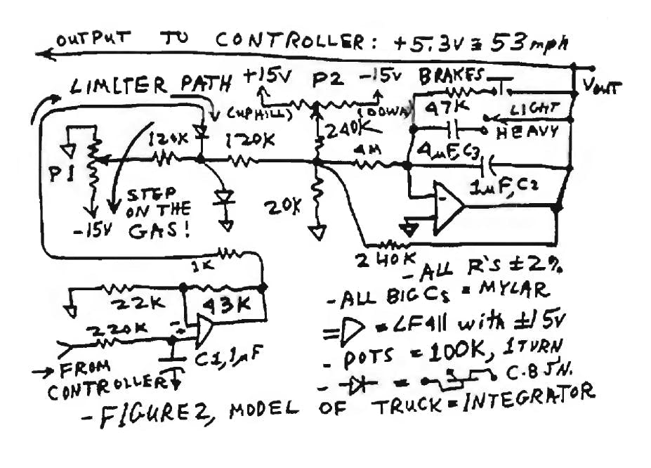
First, I built the "model" of the truck (Fig. 2 of the previous column), and by turning the pots, I could make the "truck's speed" increase (by "stepping on the gas") and decrease, as expected. Hey, a truck trying to pick up speed is JUST like an integrator. (Well, like a leaky integrator, because the faster it goes, the less it's able to accelerate fast. And if you take your foot off the gas, it tends to slow down.)
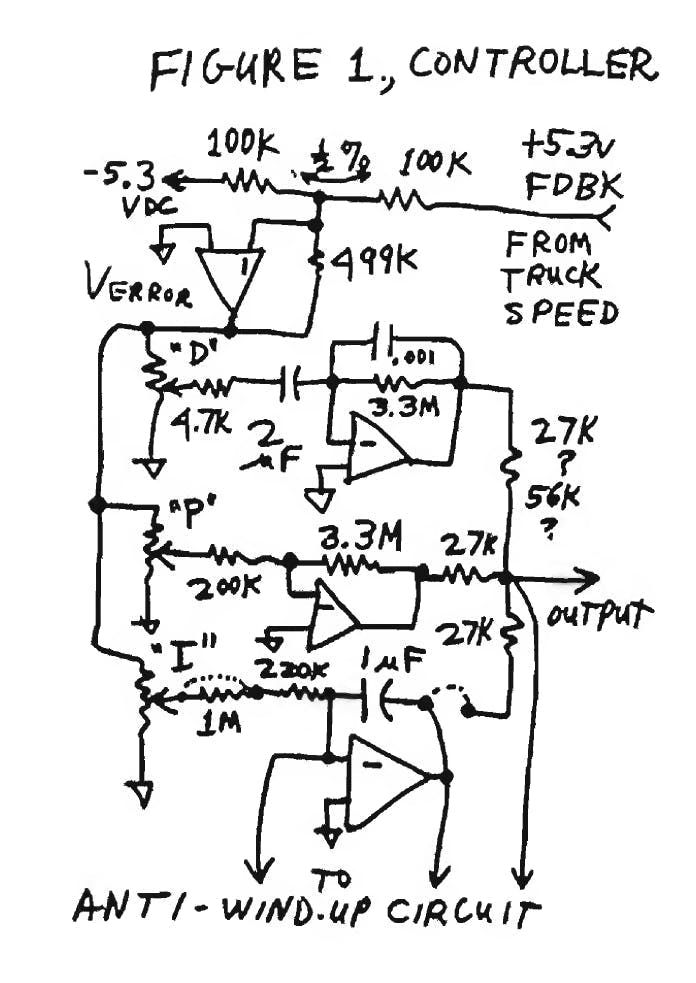
Then I built the main PID servo (Fig. 1 of the previous column). With the integrator disconnected, I connected it up to the "truck model" and started it up. The P and D terms alone made a surprisingly crisp servo. All I had to do to get fast settling and no overshoot was to set those two pots at 100%. Swoop, the output "accelerated" right up to "53.4 mph," ±0.5 mph, and held there with no overshoot (Scope photo 1).
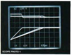
The vertical scale factor is 2 mph per division, at *0.835 seconds per horizontal division. Looking at the three lower waveforms, the one on the left shows the "speed" of a lightly loaded ("8-ton") truck with fast acceleration, and the middle one reveals a heavily loaded ("40-ton") truck, accelerating at a slower rate. The right waveform shows the "8-ton" truck on an "upgrade." You can see that the limiter is stable for all kinds of loads and biases. The upper waveforms are just the outputs of the differentiator. In a short while we'll discuss why it worked so well, and why I picked the R and C values that I did.
Now, with just the P and D amplifiers connected, the gain was not infinite. The proportional path had a gain of about 5 × 16 = 80. Therefore, if one was "driving uphill" as fast as it would go on a steep upgrade, there would be a little error, perhaps -0.3 mph (i.e., 53.1 mph), which was necessary to let the throttle go nearly wide open (-7 V). Conversely, if the "truck" was on a "downgrade," the speed error might be +0.3 mph, because the main servo path had to pull the gas pedal "up" until it was nearly off (-0.2 V, e.g.)—even if the driver kept his foot FLOORED. Some people might say that ±0.3 mph with no overshoot is pretty good. It's acceptable to many truck drivers. But I wanted to make it much better. (Have you ever seen any Fuzzy Logic (FL) controllers that had accuracy better than that on upgrades and downgrades?)
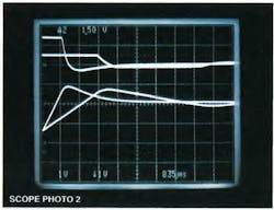
Next, I connected up the integrator stage. Sure enough, the integrator would "wind up" and cause a 1.8-mph overshoot as the speed limiter was starting to cut in—up to 55.2 mph—exactly as I had expected. See Scope photo 2 with the same two "trucks." But after it settled, the integrator would trim the error to exactly 53.4 mph, as desired. Not too bad!
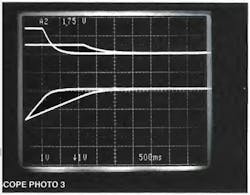
Then I added the anti-wind-up circuit. Son of a gun, that worked, too! It kept the integrator's output at 0 V until the speed limiter began to cut in. Now, the speed would rise right up to 53 mph ±0.2 mph, and promptly settle out to 53.4 mph, exactly, within better than 0.1 mph. That's what I expected (Scope photo 3).
I fooled around with higher gain and lower gain, and things worked as expected. I fooled around with heavier versus lighter trucks. I even got data (and a scope photo) on an "88-ton truck," but we decided not to print it because it was very well-behaved and boring. The control was always well-behaved. I tried cutting back on the gain for the D term and got some slow overshoot. It wasn't really BAD, maybe 0.5 mph. That's what I had anticipated. Then I set that gain back to 100%.
I varied all of the gains for the integrators AND everything else. The response was pretty clean in every case. I didn't have to make any major or minor adjustments to get the response to be well-behaved. Even when I changed the truck's gear ratio, it was well-behaved. You may notice, though, that the settling of the limiter wasn't quite as "crisp" when the integrator was added, compared to Scope photo 1. There's a little "settling tail." Maybe the PID system isn't perfect, but it's pretty good, and it settles well inside 0.1 mph error in just a couple of seconds.
What components did I change in Figure 1 of the previous column? All three pots wanted to be up near 100%. The input resistance for the integrator worked slightly better at 200 k than at 1 M. The input resistor for the P term still worked well if I paralleled it with another 200 k. That means I had a lot of safety margin, but I left it at 200 k. I didn't have to change the basic differentiator much. But the resistor from the D term to the output wanted to be changed from 27 k; to 56 k, so that the differentiator couldn't overpower the other terms and turn off the anti-wind-up too early. In the anti-wind-up circuit, the 1-µF capacitor in the detector that fed the limiter worked slightly better when changed to 0.1 µF (Fig. 4 of the previous column).
I set up some more experiments with and without the anti-wind-up circuit. If the anti-wind-up circuit wasn't provided, it sure did overshoot significantly—not bad enough to fail a test, but bad enough to look crummy.
Some proponents of FL have stated flatly that it would be impossible for any conventional controller, such as a PID type, to cover such a wide range without oscillating. But you just witnessed how it worked well in two worst-case conditions: heavily loaded, and lightly loaded. It also worked at in-between values.
Some FL experts claimed that a conventional or PID approach couldn't possibly work well if the controller wasn't linear. I built some nonlinear circuits in the controller, so the gain at the controller input could be halved or doubled at low throttle settings or at high. It was impossible to see any difference in the results.
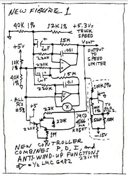
Now, that circuit I showed in the previous column was designed to be very versatile—and it was. But it was also quite complicated. So, my plan was to determine the correct coefficients of gain in that circuit, and then execute that function with a much simpler circuit (New Fig. 1).
This controller is to be hooked up to the basic Figure 2 of the previous column. I engineered this to work the same as the old Figure 1, but with simpler capabilities and less expensive parts.
Note that this circuit is definitely simpler. Instead of using four op amps to make the null amplifier and PID controller, this circuit only requires a dual op-amp. Rather than employing four op amps to make a detector and anti-wind-up circuit, I used a couple of transistors and 1/4 CD4066 to reset the integrator and keep it from causing any errors.
Will this circuit work well under all road conditions with all loads? I'm sure it will. Just because I haven't yet built it does NOT mean that it's NOT certain to work.
Next hack: could we use this controller to act as a speed limiter for a high-performance car? How about a vehicle like a Corvette or a hot Mustang that could accelerate at around 0.5 G even at 50 or 80 mph? Perhaps. But obviously, the input to the throttle controller wouldn't work well with 0.3 seconds of lag. It would require more like 0.1 second.
I COULD chop the 1-µF feedback capacitor in the vehicle's model to 0.1 µF to simulate a high power-to-weight ratio. Plus, I could cut the lag of the controller actuator and run this in real time.
But I actually decided that this is an analog computer, and to simulate a car 10 times faster, I would just declare the time scale changed by a factor of 10. I had proven already that it worked, so I didn't have to rebuild the circuit. This was reasonable, especially be-cause nobody wants to buy such a speed limiter.
In conclusion, when an EXPERT on FL claims to have a scheme that's much better than any conventional controller, he may not know that he's only comparing his FL system to a mis-applied or far-off-optimum conventional circuit or system. For years1,2,3, I have been saying that in most cases, if you find out how the comparison is made, you may be able to show that a conventional (PID or similar) controller or system can actually do better than the best available FL-based system.
This is partly because it's sometimes not easy to optimize a FL system. It might take a lot of work to get the FL system working well, especially if things are complicated or nonlinear. If an FL controller has P and D terms but not any I term, then it might have trouble competing with a well-designed PID system because it doesn't have infinite gain at dc.
I also have said previously that I often agree that some systems based on FL are excellent, compared to conventional systems. BUT—not the one in the article that raised all of these questions.
Furthermore, it's true that FL may provide advantages if there's a lot of nonlinearity in the system, or if the controller will work better if it is nonlinear. In that case, the FL system might work quite well—after a lot of study and work. Just don't forget that the conventional system also can have nonlinearities built in.
How well does my PID controller respond when you ask it to respond to an upgrade or downgrade? Does it respond as smoothly and precisely as the FL controller? I would love to plan some comparisons. I have yet to connect my controller to a real vehicle. But at least the model of the truck worked well, with plenty of gain to hold negligible error on "upgrades" and "downgrades."
Plus, I didn't need many trims or adjustment to go from one kind of "truck" to another. My standard controller was well-behaved in each case, even if the "actuator" was nonlinear with steeper gain at some settings and less at others.
Now, do you have to purchase op amps and 1-µF capacitors in order to take advantage of my best controller scheme? Heavens, no. You could execute my PID with anti-wind-up with any number of PID controllers. It could be executed with analog circuits, straight digital, DSP, or even FL. But if you want it to work well, you need to understand the signals, the circuits, and the principles behind the analog circuit. If you don't understand all of that, then you might say something foolish, like: "Conventional controllers are OBVIOUSLY inferior. They couldn't POSSIBLY perform this task, so we won't even try one. We'll just build an FL controller." Bad idea!
In fact, I know one guy who started out his planning for an FL system by building an analog system, which is easy to get a feel for. Then he took the best analog system and added refinements, nonlinearity, etc.—and executed it all in FL.
Am I going to put a speed limiter on my Beetle to keep it down below 72 mph? Heck, no. That wouldn't be safe. I have better ideas.
So, what's my point here? As I often say, "The sudden cessation of my stupidity is worthy of some note." And if you see FL Experts claiming that they can do things that nobody else can, QUESTION AUTHORITY.
Is it just possible that they have an "excellent system" that's excellent only in comparison to a mis-applied "conventional" controller? Is it possible that they have designed a steam-pressure controller that won't regulate pressure when you begin drawing steam? Is it possible that they have designed a truck-speed controller that will hold the speed constant only until it comes to an upgrade?
Oh yeah, I was going to explain why I picked the components that I did. The "truck" acts as an integrator with unity gain at 3 mHz from the "gas pedal" to the voltage that represents the speed. If I add a gain of 80, it would make the loop have unity gain at 240 mHz. Then there's a lag of 0.3 seconds (estimated) added into the controller path.
That's seen as a lag at a frequency of 0.5 Hz. If I can keep the loop closure below 0.24 Hz, that shouldn't be too close. It might cause a bit of ringing, but I can tweak that out by adding the differentiator.
The lightly loaded truck now looks like an integrator (i.e., just like an op amp) with unity-gain crossover at 0.24 Hz, plus an extra lag at 0.5 Hz. If the main feedback path is a gain of 80, it would be wise to add a lead (gain boost) at frequencies above 0.5 Hz, which means a differentiator with a gain of 80 at 0.5 Hz. That's what you get with a preamp gain of 5, feeding a differentiator at 3.3 seconds. The effective differentiator is at 16.5 seconds, or 60 milliradians/s, or 9 mHz. When will this gain get up to 80? At about 720 mHz. Not bad! That's what I chose from scribbling on the back of envelopes. It worked the first time with no overshoot. This is for the worst case, with a lightly loaded truck. For a truck loaded much heavier, such as five or 10 times heavier, the integrator has a unity-gain crossover at 0.048 or 0.024 Hz. This kind of "op amp" or "integrator" is even easier to close the loop around. It's even more stable.
All for now. / Comments invited!
RAP / Robert A. Pease / Engineer
[email protected]–or:
Mail Stop D2597A
National Semiconductor
P.O. Box 58090
Santa Clara, CA 95052-8090
References:
- Pease, Robert A. "What's All This Fuzzy Logic Stuff, Anyhow?" Electronic Design, May 13, 1993, p. 77.
- Pease, Robert A. "What's All This Fuzzy Logic Stuff, Anyhow? (Part II)," Electronic Design, Nov. 1, 1993, p. 95.
- Pease, Robert A. "What's All This Fuzzy Logic Stuff, Anyhow? (Part III)," Electronic Design, Nov. 11, 1993, p. 105.


About the Author

Bob Pease
Bob obtained a BSEE from MIT in 1961 and was a staff scientist at National Semiconductor Corp., Santa Clara, CA, for many years. He was a well known and long time contributing editor to Electronic Design.
We also have a number of PDF eBooks by Bob that members can download from the Electronic Design Members Library.
Comment About the Article
To join the conversation, and become an exclusive member of Electronic Design, create an account today!

Leaders relevant to this article: