We often think of Ohm's Law as V = I × R. That's not really Ohm's law, but we'll use that relationship today to measure V = I × R for some large currents. Specifically, I need to design a good 1-mΩ shunt to sense 15 A. Yes, you can go out and buy shunts in the 1- to 1000-mΩ range.* But the small ones are too small, the big ones are pretty expensive, and none are really easy to buy.
I'll show you how I designed a couple of shunts that can easily dissipate 22 W without harm (but with minor loss of accuracy). Because this is rated to run at 225 mW, 1% of full power, it shouldn't cause too much error. Next month, I'll show you what we can do with them!
The resistance of 22-gauge copper bus is just 16 mΩ/ft, if you believe "The Book." But that's just the rated or worst-case value. When you measure it, you'll find that it's really about 13 mΩ/ft. So paralleling 12 9-in. lengths of that wire will make about 1.0 mΩ. Just connecting the wires as a bundle, though, would be too small to dissipate 20 W. The heat would be too congested.
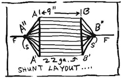
So my best structure arranges the wires like a bird cage to spread out that heat. I'll make a couple of 6-in. buses A-A' of bus wire to support the 12 9-in. wires between the buses. But I can't just connect my 15 A to the buses. That would be too crude, and the current wouldn't be shared properly among all of the wires. I will make some sharing conductors to ensure that each of the 12 wires gets the same current. I'll put in 12 bus wires of ~14 gauge, each 1.5 in. long. These 12 wires (each with about 1.1 mΩ) can connect a point A" to the bus A-A' (see the figure).
How can this work? Easy. Bend that bus in a circle, then connect A to A'. Similarly, point B" is connected with 12 wires to Bus B-B'. Points A" and B" are provided with Force and Sense connections. Then we have a 1.0-mΩ> shunt. Points A" and B" are well ballasted and the heat is well spread out, distributed over all of the wires. This shunt will get pretty hot when you run it at 22 W, but not hot enough for the solder to melt. Will I have to test it at 144 A? No, I can just build one strand and run 12 A through it. The rated fusing current for 22-gauge wire is 40 A, so 12 A isn't bad.
Fortunately, we have a basic shunt design that can be made up in under half an hour for less than $1, and you can pick the wire gauge, and the lengths and numbers of conductors, to dissipate almost ANY amount of heat for any number of milliohms. Will the bus A-A' carry any current? Not any significant current, as the symmetry forces the current to mostly flow past the wire. So if that circular bus were made of #24 wire and broken in several places, you wouldn't see any significant difference from 14 gauge. It's just to hold things steady and to help spread out the heat.
Unfortunately, copper has a tempco of about +3300 ppm/°C. So if you dissipate even 3 W, this shunt will warm up and drift in its r value, perhaps +0.5%. What's a mother to do? More on this later. Don't throw out this design.
Now, nichrome wire at 22 gauge has about 1 Ω/ft with a low tempco. I could lash up 42 1/2-in. long nichrome resistors, in parallel, to make a good 1-mΩ shunt. How can I lay out 42 1/2-in. wires? I placed a serpentine between two 1/2-in. by 3-in. strips of double-sided copper-clad, spaced 1/2 in. apart. I soldered up seven wires (using strong HCl flux). Then I arranged six pairs of strips in a hexagon, with heavy bus conductors to share the currents, as above.
The actual resistors would be quite small, but the copper-clad would spread the heat out. This compact hexagon would have 3-in. sides and be 6 in. across, but only a couple of inches long—compact, but not too small to spread out the heat. It might not be perfect in precision, but its low tempco (20 ppm/°C) would be better for many cases. Any shunt should be mounted in a box with some vent holes to let out the dissipation.
To calibrate these shunts, shove 1 A into the Force leads through a calibrated 1-Ω resistor at 1 V, and look for 1000 µV at the Sense leads. Add a few extra conductors to get the resistance down to the right calibration, or snip out a few to get it up there. Next month, we'll use one of these milliohm shunts in a wide-range watt-meter.
All for now. / Comments invited!
RAP / Robert A. Pease / Engineer
[email protected]—or:
Mail Stop D2597A
National Semiconductor
P.O. Box 58090
Santa Clara, CA 95052-8090
*Shunts of various sizes can be obtained from many good vendors, such as www.precisionresistor.com; (727) 541-5771.
About the Author

Bob Pease
Bob obtained a BSEE from MIT in 1961 and was a staff scientist at National Semiconductor Corp., Santa Clara, CA, for many years. He was a well known and long time contributing editor to Electronic Design.
We also have a number of PDF eBooks by Bob that members can download from the Electronic Design Members Library.

