Building Home or Very Small Office Electronic Circuit Prototypes, Part 3
This series installment will address the lab equipment that’s pretty critical to modern, but not specialized, electronics and testing it. I will first digress slightly to provide an update on the circuit boards designed and discussed in Part 1 of the series.
Circuit-Board Inspection: AC-Power-Control Isolation Boards
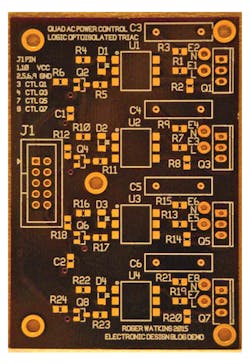
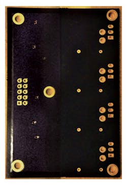
Figures 1 and 2 show the circuit board designed for Part 1. The boards were received from OSH Park a few days ago (at the time of this writing), with perforated breakaway tabs on some edges, and roughness where the tabs had been broken away on other edges. The tabs were about 3 mm wide; on my boards, two tabs were on the right side and one tab on each other side of the board as viewed from the top. The tabs were weakened by four drilled holes at the board edge, each about 0.5 mm in diameter. Tabs broke easily from the boards and a little 220 grit sandpaper smoothed the remaining roughness for those of us who hate FR4 cuts.
The boards were designed to be exactly 3.000 by 2.000 inches, and measurements taken showed 3.0075 by 2.008 inches…not bad. When I went to order the boards, the OSH Park software computed the size as 3.03 by 2.03 inches, which can be traced to a difference between PCBWeb outline layer line width of 30 mils, as opposed to 0 mils for Eagle and many other packages.
A piece of information for those who follow me: Modify the apertures of the outline trace layer or accept that you will pay extra for no more FR4 until either OSH Park or PCBWeb addresses this issue. In my case, this was only about 65 cents.
Looking at the figures, one can see really good detail for small print in the white silkscreen layer. The block capitals near the bottom of Figure 1 are only 40 mils high but are still well-defined. Adjacent character features are also well-defined, and not bleeding over. The solder mask seems to be a deep purple, almost black. The finish appears to be ENIG.
In my opinion, the boards were excellent, even better considering they cost me $20.65. That was after the $10-off coupon that came with the Whizoo kit, so normal pricing would have been $30.65, still not bad for prototype boards. Close inspection of Figure 2 will show the vias on the left were nicely tented per my design, and were occasionally plugged by solder mask. I was quite happy with this result.
Lab Test Equipment and Modifications for Proper Use on Modern Circuits
Lab Power Supply
I have seen people use a fixed output power supply for test purposes, and that’s OK for firmware development after debugging the power supplies and loads. It’s dangerous at best when commissioning testing for a new circuit, since low-resistance shorts can burn stuff out before doing any troubleshooting.
To test most simple and some complex circuits, a lab needs at least one lab power supply that can limit current and voltage to the load, and provide sufficient power for the circuits to be tested. For this purpose, I chose a 30-V. single-output, 5-A supply. That gives me up to 150 W of load power for low voltages, which is more than most control and small communications applications I have encountered, but less than a decent motor-drive application or power RF application might need. Choose wisely, grasshopper.
After some looking, I found a “TMS Precision Variable Adjustable 30v 5a Dc Power Supply Digital Regulated Lab Grade” on Amazon for $52.90 delivered. That’s WAY less than what one would pay for a similar supply a few years ago. The supply arrived and is similar to older digital display power supplies used at prior workplaces, with two knobs each for voltage and current limits—one course and one fine.
Digital Oscilloscope
Good luck to those of you trying to sell me a 5-GHz scope for microwave use. High frequency translates to high dollars and ESD-fragile equipment. Remember, we are going for a home or a small office. If you have money lying around, it is your choice what to do with it. If you really must tinker with 5-GHz UWB circuits and must have a scope to look at the waveforms, get your wheelbarrow and a bunch of gold bars to trade for the scope.
When testing switching power supplies, analog circuits, and lower-frequency RF circuits, a 100-MHz range oscilloscope is a key instrument. A modern digital oscilloscope with a fairly good capture rate is extremely helpful in finding and analyzing switching power-supply noise and in catching digital circuitry behaving badly. After quite a bit of research, I found a B&K 2190D 100-MHz, 2-channel scope for $423.14 delivered.
Up to now, this scope has performed reasonably well testing switching power supplies with 1.5-MHz switching frequency, and in watching asynchronous serial wired communications. I found one quirk so far—it can cause a setting to be forced and not released without a power cycle, but this happens only when I’m fiddling with probe setups, so it’s just a minor annoyance. The probes that came with the scope were pretty standard, with a point/ground sleeve tip, a slip-over push-clip for the tip, and a clip-on ground lead with a small alligator clip on its end.
Signal Generator
A signal generator capable of square, triangle, and sine-wave outputs, from sub-hertz to a few megahertz, is very helpful when checking out digital signal paths, audio circuits, power supplies (noise injection, filter testing, etc.), control circuits, and amplifiers from dc into the lower RF frequency ranges. Higher-frequency generators are again a pricey item and may be needed for special projects. My preference is to be able to generate from about 0.1 Hz to about 20 MHz, subject to cost and availability of test equipment.
Here, I will recommend looking into eBay or other resale of used equipment to keep costs down. I tried purchasing an inexpensive signal generator from Amazon. The unit I got, a “VICTOR VC2002 Function Signal Generator with 8 Frequency Range Large LCD Display 0.2Hz-2MHZ” for $130 delivered, generated waveforms but did not have an offset adjust and had a somewhat limited frequency range for my uses. I may make it a future project to repurpose this generator using replacement guts, or at least add an external amplifier with offset adjustment. I did a quick check of eBay and found a couple of “Buy It Now” units that would be good options for those looking for a used but working generator in the less than $200 range.
Multimeter
I recommend a meter with true RMS capability for ac waveforms up to at least 100 kHz. As an aside, my old vacuum tube voltmeter was rated for ac waveforms to 5 MHz, but was not true RMS (don't ask about accuracy, as it had to be calibrated on each power-up to be decent). It might not be a good idea to just go to your local hardware or lumber store to get a multimeter, since these are generally missing several ranges that are very valuable in electronics design and troubleshooting. Some of these include a diode check, a capacitance range, a frequency counter, etc. A current range of at least 10 A will be quite useful.
For most hobby uses, a 1% meter will probably be good, but for professional use, a 0.1% meter is a much better choice. I presently use a multimeter purchased from Radio Shack some years ago. An ability to resolve to about a millivolt is also extremely helpful. There are several good choices at Digi-Key and Mouser in the <$150 range.
A check of eBay turned up used Fluke 87 and 187 multimeters as “Buy It Now” items selling for under $200. For professional use at an office, my leaning would be to the Fluke 187. They don't make these anymore, but they were 0.1% true RMS handheld units that were very accurate and repeatable, and would resolve in the microvolts and microamps. Of course, lots of other choices are out there, and many of them would be equally acceptable or possibly better depending on what you intend to do with your lab.
Probe Modifications and Building
Just because you have a multimeter, power supply, signal generator, and oscilloscope doesn’t mean you’re ready to go. Those separate leads on your multimeter easily create an antenna loop that causes bad readings where measurements were expected. The BNC-to-alligator cable supplied with the function generator isn’t going to work well in most modern SMT circuits; there’s just not enough space. The oscilloscope probes that came with the scope had black alligator clips on the ground leads, and those often short or just don't grab the small pins that have ground near the tested point. The power-supply leads as supplied were very large with alligator clips on them. Sorry to say, but very few of the inexpensive test equipment choices will come with probes or leads that are good choices for real lab use.
The first modification I made was to buy some banana-to-mini-grabber leads for my multimeter years ago. Today, for voltage measurements on small circuit boards, I have 22AWG zip cord with stackable banana plugs on one end (red and black) and micro-grabbers on the other end. I also have a set of miniature (Pomona calls them replaceable precision tip probe) multimeter leads, and the silicone insulation avoids the soldering iron “oops” that decorates many sets of leads during the heat of troubleshooting. For current measurements, I generally use 20AWG zip cord with stackable banana plugs and mini-grabbers, to handle up to five or so amps.
For the function generator, get a BNC-to-mini-grabber cable if you only have a BNC-to-alligator. You will thank me later. A BNC T and a 50-⦠load will be very helpful if you plan to test above about 2 MHz or are using more than about a meter of cable.
For the oscilloscope, make or get (I made) a means that allows you to change the ground lead on the scope probe from the alligator it probably shipped with to a micro-grabber, a mini-grabber, and a smd-grabber, and whatever else you think will be needed. Nothing is more frustrating than not being able to get a ground when troubleshooting with an oscilloscope. I also like to design RF and noisy circuits (power control, motor drive, RF, etc.) with ground pads and test pads close together, where I expect to need them, so I can use the spring ground sleeves that fit over the probe tip when the grabber is removed.
For the power supply, you will want stacking banana plugs with wire that can handle the current needed, and probably grabbers that can also handle the current. I have gone so far, for a 16-V 60-A dc power supply at work, as to make ring terminals and 8AWG leads with macro-hooks on the ends to test a motor-drive application. I haven’t seen much use for the almost-always-supplied-with-power-supplies alligator clips on the end of non-stacking banana plugs with about 16AWG wire.
For testing, I prefer paired wires to avoid noise when hooking signals between boards. Generally a tight-twisted-pair is good for low-frequency signals; coax with grabbers or zip-cord with grabbers can work with dc to about 20-MHz signals. At higher frequencies and longer lengths, one gets driven to coax with better and better board interfaces.
What I refer to as tight-twisted is made by taking two wires and clamping one end together, putting the other end in an electric or cordless drill, and running the drill until the wire has a diameter of two wires together and almost round, with one turn per about two diameters of the insulated wire. I use a hot-air gun carefully to heat-relax the insulation after twisting and before removing from the drill, then heat-shrink or tie-wrap to keep the ends from slowly working loose. Tight-twisting is also marvelous for power-supply leads, as it somewhat decouples the load noise from the power-supply noise, and forces the load bypass capacitors to do their job. After some use, the twist will become a little less tight, but that has never been a problem for me.
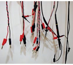
In Figure 3, the far left shows two stackable banana plugs connected to a tight-twisted pair of red/black wire, with the other end being two non-stackable banana plugs (to use up my old stock). Next in from the left are red and black discrete-wire/stackable-banana-plug leads (same at the other end near the center). Above the banana plugs for the discrete-wire/stackable-banana-plug leads can be seen a pair of micro-grabbers on a 22AWG red/black zip-cord. Near the tight-twisted pair at the center of the photo are the stackable banana plugs on 20AWG zip-cable going to the red/black pair of mini-grabbers just left of the oscilloscope probe. Behind the mini-grabbers is a coax cable that expands to a lighter-red mini-grabber behind the oscilloscope probe, and a black mini-grabber below same. The BNC connector for that coax is below on the right side of the photo.
The oscilloscope probe shown has been modified. Originally supplied with a medium-to-small alligator-terminated ground lead, the end with the alligator was snipped and a 25- × 25-mil square female connector installed. It’s shown with a “SMD grabber” having a 0.025-in. square pin that inserts in the female connector to make a fairly clean termination. The SMD grabber is at the far right of Figure 3.
When I purchased several of the discrete-wire/stackable-banana-plug leads, I cut about half of them and terminated those with mini-grabbers. There are two stackable banana plugs near the center top of Figure 3, but the grabbers didn’t reach down far enough to be in the photo (short cable ~18 in., the shadow of tips of the mini-grabbers is visible near the top above the leftmost set of micro-grabbers).
About the Author
RWatkins
Consulting Engineer
Roger Watkins is an Ex-Navy Submarine Officer, having completed Submarine Officer and Submarine Nuclear Engineer qualifications. He has consulted, designed electronics, written software/firmware, searched patents, and managed design teams for several companies over many years, including:
- Analysis & Technology Inc. (acquired by Anteon International, today part of General Dynamics Information Technology)
- Lake Shore Inc. (today Oldenburg Group Inc., Defense)
- Caterpillar Inc.
- Quill & Disc Inc.
- Validus Technologies LLC
- bb7
- Intellihot Green Technologies


