Four-Wire Sensing Can Make or Break Your Measurements

In low-voltage and high-current applications, it is common to use a measuring instrument capable of four-wire sensing to help minimize the effects of resistance between connections (such as wire resistance, alligator-to-pin resistance, alligator-to-alligator resistance, and so on) to avoid inducing a significant voltage drop on those paths.
However, disaster can strike when sensing is implemented erroneously, increasing both the magnitude of error (instead of measurement accuracy) and the number of wrinkles on one’s forehead. Avoiding such calamities requires a firm grasp on the underlying principle of how sense lines work and taking the utmost caution in the practice of such a witty method.
Four-Wire and Two-Wire
What is four-wire measurement and how does it differ from the ordinary two-wire measurement? Four-wire sensing or four-terminal sensing, as Wikipedia describes it, is “an electrical impedance measuring technique that uses separate pairs of current-carrying and voltage-sensing electrodes to make more accurate measurements than the simpler and more usual two-terminal (2T) sensing.” Further annotation by Wikipedia explains the concept as “…a pair of sense connections (voltage leads) which are made immediately adjacent to the target impedance, so that they do not include the voltage drop in the force leads or contacts.”
Take, for example, a 5-V source connected to a 2-A load through metallic meter sticks. If the meter sticks each have a 1-⦠resistance, then the potential developed at the load would only be 1 V. However, by introducing a feedback path (the sense lines) that could say to the 5-V source, “Hey! I’m only receiving 1 V here, so you better increase to 9 V?,” then the correct/desired voltage level will be impressed at the load. It is self-evident that a two-wire measurement setup can’t achieve this self-correcting mechanism due to the absence of the feedback path.
How the Four-Wire Setup Works
So the four-wire method is an effective setup for compensating drops on low-resistance paths. But how does it do it electrically? Figure 1 shows a simple schematic of a four-wire setup.
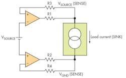
As with nearly all feedback paths in electronics, a four-wire schematic would have the ever ubiquitous operational amplifier. Due to the op amp’s impressively high input impedance, it serves as a perfect candidate for sampling voltages in your circuit without having a significant effect. This characteristic is effectively taken advantage of in a four-wire setup because of the implication that there will be an infinitesimal voltage drop at R3 and R4. Voltage drops at the sense lines are highly undesirable because that is where the true developed voltage is sampled.
From a block-level perspective, the schematic looks like two voltage followers, one voltage follower tracking the high end and the other tracking the low end (or ground potential).
A Danger in Four-Wire Sensing
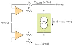
The four-wire setup has to be practiced with utmost caution in lieu of the possible scenario demonstrated in Figure 2. What happens if one of the SENSE pins is accidentally left floating (like when a cold solder breaks loose or an alligator clip snaps free)? The SENSE lines are now telling the source to keep increasing its voltage because it is just reading a high-impedance (i.e., approximate 0-V reading).
Eventually, the FORCE lines (R1 and R2) will keep increasing the bias level until the preset current limit is reached, possibly destroying the device under test (DUT), or worse, damaging the supply (though a supply is rarely damaged this way if it was manufactured for industry use).
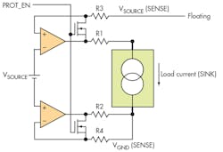
One way to avoid damaging the supply is by connecting a switch between the SENSE and FORCE lines (Fig. 3). The PROT_EN signal creates a short between the force and SENSE lines when the supply voltage reaches a threshold (maybe on a level that corresponds to the preset current limit).
Proper Placement of Force, Sense Terminals
Choosing where to sample voltage (or where to place the sense lines) is crucial to accurate measurement. I recently had a debate with my colleagues regarding measuring the characteristic of a low-dropout regulator (LDO). There were two bias points for the LDO: one served as the supply for the protection circuits and extra features of the entire chip (of which I can’t disclose), labeled as VIN; and the other as the supply for the main forward path (through the pass transistor), labeled as VINLx.
Their argument is that the SENSE line should be connected to VINLx, while the FORCE line should be connected to VIN. My argument is the other way around, because VINLx would draw most of the current that would flow through the pass transistor (so the FORCE terminal should be connected to VINLx).
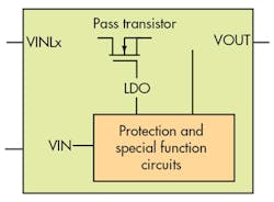
Looking at Figure 4, what is your opinion on the matter? Should the FORCE terminal be connected to VINLx and the SENSE terminal to VIN, or vice versa?
About the Author
Justin Spencer Mamaradlo
Senior Design Verification Engineer
Comment About the Article
To join the conversation, and become an exclusive member of Electronic Design, create an account today!

Leaders relevant to this article: