A Simple RS-232-Based Logic State Analyzer
Written by Jacob Mathews for the Oct. 16 2000 issue of Electronic Design
Designers are often faced with debugging and testing new hardwareor software while operating in-circuit in the application hardware. Test points and/or headers are generally provided to make monitoring the hardware status more convenient. Critical control and data signals are often captured on a logic state analyzer (LSA) to verify and validate functionality.
Capturing the operating state in multiple-card systems for testing can be made cumbersome by several factors. For instance, in field or remote situations, all test points may not be terminated or accessible. In addition, hardware probing using an instrument-grade LSA may be inconvenient. Non-processor-based hardware also can make troubleshooting more difficult.
If the system status could be captured and made available via an RS-232 link, then the captured data could be downloaded to a PC and used for monitoring and analysis. This circuit emulates just such a low-cost, simple logic state analyzer that can be constructed using a few off-the-shelf components (Fig. 1).
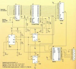
The reference clock/write signal of the board under test (BUT) is applied to U2 as the FIFO write signal. Register U1 offers low data synchronization with reference to the clock/write signal. Control and data, the signals to be monitored, are fed as the data inputs. The FIFO output data is fed to the U3 parallel-in-serial-out (PISO) register. For serial transfer, a baud-rate clock is generated by the 555 timer. R6, R7, R8, and C5 are chosen for the desired baud rate. The MAX233 is used as the RS-232 line driver/receiver.
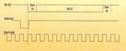
Data fills the FIFO continuously until a FIFO-full condition occurs. Since U4A is pulled up, the logic-high input is normally shifted out by the PISO. The FIFO read is issued from the PC side using the TX line under program control by writing 0xff to the serial port. After synchronizing with the timer clock using U4B, this read signal is used to read the FIFO and load the result to the PISO register. During the read, the MSB (Q7 of the FIFO) is latched into U4A. The timer shifts the data serially at the baud rate (with start and stop bits added), which is then received at the PC (Fig. 2). Note that before every fresh capture a low on the RTS line is issued. This is used to reset the FIFO.
(Editor's Note: The source code listing for this Idea For Design is no longer available.) Using Visual C++, the capture function can be embedded into GUI, resulting in a simple virtual LSA. To incorporate larger data widths and deeper capture depth, the circuit can be expanded using additional FIFOs and PISOs. Note that the FIFO write pulse width and write recovery times will constrain the capture rates. If required, the CTS line can be used to indicate a FIFO full/empty condition.
When monitoring hardware status intermittently, the FIFO can be eliminated and the register output can be applied directly to the PISO input. The required circuitry can be easily absorbed in the system FPGA (except for the MAX233) and the baud-rate clock can be derived from the system clock.
About the Author
Comment About the Article
To join the conversation, and become an exclusive member of Electronic Design, create an account today!

Leaders relevant to this article: