Attaining Phase Coherency for Multiple Data-Converter Systems
This article is part of the TechXchange: Antenna Design 101
Download this article in .PDF format
Electronic beamsteering is a fairly old technology and dates back to around 1905, when Karl Braun demonstrated phased-array transmission of radio waves to improve directionality. The same principles were used on early radar systems during the Second World War. In principle, phased-array systems employ a series of equally spaced antennas, typically a quarter wavelength apart, that use constructive and destructive interference of the transmitted (or received) signal, resulting in a directional vector.
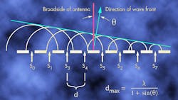
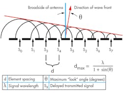
In general, there are two types of phased-array antennas: static and dynamic. Static phased-array antennas are used to improve directionality of transmission and null certain vectors to diminish interference with other systems. Static phased-array antennas have a fixed-interference pattern and result in known vectors. To steer the beam of a static-phased-array antenna would require it to be mechanically moved. Dynamic-phased-array antennas use several electronic methods to either delay the RF signal’s arrival or shift the phase of the emission at the antenna elements. Both methods result in patterns that form a predictable transmission or reception vector (Fig. 1).
There are many advantages to electronic beamsteering over mechanical methods. Electronic steering can sweep much faster than a mechanical antenna, allowing systems such as advanced radars to track and search at the same time. Another advantage is the ability to dynamically change the sweep pattern. By applying pseudorandom patterns to the sweep vectors, military radars can avoid countermeasures by removing predictable patterns of emission (for example, a given sweep period).
Electronic-warfare (EW) receivers, also known as early-warning-detection receivers, use similar concepts to phased-array radar systems. These receivers are designed to indicate threat vectors to operators and pilots in order to avoid either detection or direct threats such as missile defenses.
These EW receivers use one of several methods to detect the threat by angle of arrival (AoA). EW antenna systems can perform AoA based on amplitude comparison, which simply compares the relative power level at each antenna element to calculate the emitter vector. These systems can also use time difference of arrival (DTOA) or other methods based on interferometry.
In addition, with available spectrum for communications also diminishing, the use of dynamic beamsteering is also finding its way into the next generation of cellular infrastructure for spatial multiplexing, as well as adaptive beamforming found in systems such as advanced Wi-Fi hotspots. This allows operators to effectively “farm the land” multiple times by allocating spatial vectors along with coding or frequency assignments, which provides another method for adding users.
Phase-Coherency Requirement
With the availability of ultra-high-speed data converters and components designed for direct RF sampling, engineers have begun to remove the complex phase-shifting systems used in early radars and other dynamically steered phased arrays. The data converters are being moved closer to each element, providing a great deal of flexibility. The same applies to EW and wireless infrastructure systems.
One advantage is the ability to gently degrade on failure. For instance, in a system with a limited number of data converters along with phase shifters at the elements, a failure of one converter could dramatically reduce the effectiveness of the system. However, if there are individual converters per element, then the loss of a single channel would not dramatically affect system performance. Another advantage is the ability to repurpose sections of the array and dynamically reconfigure the system based on mission or loading.
All of these capabilities rely on deterministic sampling of the RF signals—both received and transmitted—which provides the necessary phase information. This is less complicated when there are limited numbers of data-converter channels. However, as the industry moves to elemental beamforming, the challenge of phase aligning all data converters becomes increasingly difficult.
Data Converters and Deterministic Latency
Several techniques are available to engineers to establish a known delay through the elements of a sampled system. In general, each channel can have either a fixed and repeatable latency, also known as deterministic latency, or the architecture must provide a method to calibrate out and phase errors inherent in the system. Moreover, designers may choose to provide both methods, which can reduce calibration time during power up.
When an analog-to-digital converter (ADC) channel samples an input, the track-and-hold section of the device locks the input level at the sample time, which allows the ADC circuitry to convert that analog sample to digital bits. All converters will have some amount of latency between when the sample is locked to when the output bits are available.In a multi-converter-based system, slight variations in layout of the sample clock or input signal routing may introduce some differences in the delay from channel to channel. Many times this can be calibrated out since these delays are fixed by design.
However, many modern ultra-high-speed data converters use methods that may not provide the output data relative to the sample time with a fixed delay. This can be due to converter architecture, the phase error of internal phase-locked loops (PLLs) used to generate clocks, as well as methods of data serialization. This applies to both ADCs used in the receive chain and digital-to-analog converters (DACs) used in the transmitter (or radar exciter).
Establishing Phase Coherence
Most all ultra-high-speed data converters implemented in modern RF systems have done away with parallel interfaces, and migrated to serialized data. This is due primarily to the large number of parallel transmission lines required to transport the digital data.
For instance, the ADC12D1600 is a 3.2-Gsample/s, 12-bit ADC that requires 96 electrically matched transmission lines (48 pairs), plus the clock pair to be routed to an FPGA or ASIC. In contrast, the ADC12J4000, a 4.0-Gsample/s 12-bit converter, uses a JESD204B serialized interface that requires only 16 transmission lines (8 pairs) along with two additional clock pairs in a 10- × 10-mm package.
When data is serialized, the clock is embedded into the stream, thus removing the requirement to match the electrical length of the clock to the data lines. However, the data rates may not be locked to the sample clock due to framing or transport overhead (for example 8b/10b encoding). Another source of mismatch could be delays caused by mismatching of data lanes stemming from the location of the data converters and processing elements (such as an FPGA) on the printed circuit board (PCB). These uncertainties can cause the actual sampled data to arrive at the processor or FPGA at different times, which is unacceptable in a phase-coherent system.
Delivering Deterministic Latency
Several methods that provide deterministic latency can be used to address these issues. The JESD204B interface standard introduced subclasses to provide backward compatibility with older revisions, and includes a new methodology to establish phase coherency between data-converter devices.
As mentioned, this interface can run faster than the individual channels of an ADC or DAC. This speed produces uncertainty of when the sample was actually acquired, once the data is deserialized (for instance, returned to parallel data within the processing elements).
Both JESD240B subclasses 1 and 2 provide a means to establish deterministic latency between individual data-converter devices located together on a circuit card assembly (CCA). Though each mode requires matching of the device and system reference clock, they relax the need to match data lanes, which are the majority of the PCB traces.
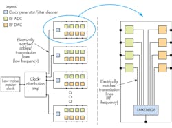
If there are large numbers of CCAs, a low-phase-noise master RF clock can be provided to all boards though matched transmission lines or media, such as coaxial cable. In many clock generators, such as the LMK04828, there are mechanisms to adjust the phase of these master clocks to “tune out” any mismatching between the master clock source and each CCA (Fig. 2).
Each JESD204B receiver block has an elastic buffer that allows for lane mismatching. During the initialization processes, the maximum latency is determined by the receiver block. Next, a point is chosen relative to a local clock (the local multi-frame clock, or LMFC) to allow all lanes to be released in-phase. This guarantees that all samples are aligned and coherent.
Another method doesn’t need any form of known latency between clocks, but may require a fairly deep data buffer and uses live calibration. This can be accomplished in two major ways. First, latencies may not be consistent from one power cycle to the next, so calibration must be done every time the system is powered up, or when a JEDS204B link is lost and reestablished.
A mechanism is required to switch to an external calibration pulse, which arrives coherently (or via a known and fixed delay) for every channel. In this mode, the system can then look for the calibration pulse and determine how much difference exists between samples and adjust the buffer release point for each converter channel. This can be done in combination with subclass 1 or 2 to reduce the time it takes to calibrate out the phase uncertainty.
The second major way is to use timestamping. Many modern high-performance data converters, such as the ADC12J2700, have a timestamp input. When this mode is enabled, the timestamp input is sampled coincidentally with the analog inputs. The state of the timestamp input is placed in the least significant bit (LSB), effectively reducing the converter’s dynamic range by 1 bit (approximately 6.02 db).
Placing the calibration pulse on the timestamp input allows the same method of phase adjustment, but without the RF input switches required to inject the calibration pulse. It greatly simplifies the calibration electronics and actually provides a digital means to phase-align the converters.
Conclusion
As dynamic phased-array antenna systems take advantage of the availability of ultra-high-speed data converters to improve flexibility and performance, the need to maintain phase coherency across large numbers of data converters is an ever-increasing challenge. With the introduction of the JESD204B interface standard, mechanisms for establishing deterministic latency are available to designers. These methods alone or in combination with various timestamp and calibration methods can provide system-wide phase coherency across large numbers of data converters.
Read more articles like this at TechXchange: Antenna Design 101
References:
Datasheets: ADC12D1600, ADC12J4000, ADC12J2700, LMK04828.
JEDS204B interface.
About the Author
Richard F. Zarr
Richard Zarr is a technologist at Texas Instruments focused on high-speed signal and data path technology. He has more than 30 years of practical engineering experience and has published numerous papers and articles worldwide. He is a member of the IEEE and holds a BSEE from the University of South Florida as well as several patents in LED lighting and cryptography.
Comment About the Article
To join the conversation, and become an exclusive member of Electronic Design, create an account today!

Leaders relevant to this article: