Bootload Wirelessly Using the Bluetooth Serial Port Profile
A bootloader makes it possible to update a product’s firmware in the field. Common communication interfaces like UART, I2C, SPI or USB can be used to update the firmware, which typically involves a wired connection between the bootloader host and the target. With the help of a Bluetooth-to-serial adapter, the same bootloading operation can be performed wirelessly. This becomes extremely useful if the target is located in an area that’s very hard to access physically or if the target is inside a sealed enclosure.
To use a bootloader, one must first configure the product so that the bootloader, and not the application, is executing. Once the bootloader is running, the host can send a “start bootload” command over the communication channel. If the bootloader sends an “OK” response, bootloading can begin. During bootloading, the host reads the file for the new application, parses it into flash write commands, and sends these commands to the bootloader. After the entire file is sent, the bootloader verifies the file’s integrity and then passes control to the new application.
This file type includes high resolution graphics and schematics when applicable.
Wireless bootloading using a Bluetooth-to-serial adapter can be performed on any target that supports a UART bootloader—without any modifications to the host or the bootloader firmware running on the target—using the Bluetooth Serial Port Profile (SPP). Bluetooth profiles are additional protocols on top of the Bluetooth Core Specification that specify general behaviors used by Bluetooth-enabled devices to communicate with other Bluetooth devices having the same profile.
The Serial Port Profile (SPP) is based on the RFCOMM (Radio Frequency Communications) protocol that emulates RS-232 serial ports. It defines how to set up virtual serial ports between two devices and how to connect them with Bluetooth. A PC with Bluetooth can connect to the Bluetooth serial adapter on the target side and perform a bootload operation. A bootload command can be triggered wirelessly by sending a serial command to the application currently running on the target device.
The Bootloader
Bootloading is a process of upgrading an embedded system’s firmware over a standard communication interface. The host may be a PC with a bootloader host application tool or another microcontroller. A bootloader is the first code that will be executed after power up or system reset.
The bootloader preprogrammed into the microcontroller communicates with the host to get the new application image and writes it into the internal flash of the microcontroller. After a successful bootload operation, the microcontroller starts executing the new application firmware. If a new application isn’t received from the host, the bootloader executes the existing application in the microcontroller.
The format of the application firmware image depends on the microcontroller in use. For example, a PSoC controller uses .cyacd (application code and data) as the format of bootloadable applications. By using a standard Bluetooth-to-serial adapter, the same bootloading operation can be performed wirelessly on a target that supports the UART bootloader.
The basic bootload operation remains the same while bootloading wirelessly using the Bluetooth-to-serial adapter. However, a virtual serial connection must be established between the host and target to send the application image wirelessly via Bluetooth.
The SPP defines how to set up virtual serial ports and connect two Bluetooth-enabled devices. It then allows these devices to perform a RS-232 (or similar) serial cable emulation. The scenario covered by this profile deals with legacy applications using Bluetooth as a cable replacement, through a virtual serial-port abstraction. Using SPP, the connected devices can send and receive data just as if there were Rx and Tx lines connected between them.
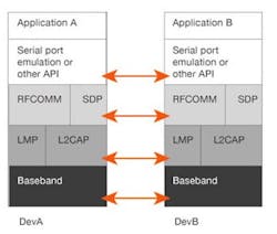
Figure 1 shows the protocols and entities used in the SPP. Baseband, LMP, and L2CAP are the OSI layer 1 and 2 Bluetooth protocols. RFCOMM is the Bluetooth adaptation of the GSM TS 07.10 standard used by GSM cellular phones to multiplex several streams of data onto one physical serial cable, providing a transport protocol for serial-port emulation. SDP is the Bluetooth Service Discovery Protocol which allows a Bluetooth device to discover services offered by other Bluetooth devices and their associated parameters.
In the case of wireless bootloading using SPP, the applications running on the two sides are the bootloader host application on the PC or a UART interface on the host microcontroller and the UART bootloader on the target system.
Standard Bluetooth-to-serial adapters like the Bluefruit EZ-Link module or the JY-MCU module can pair with any Bluetooth-enabled computer and appear as serial COM ports. After pairing the Bluetooth module with the PC, there will be two serial COM ports listed in the device manager. This occurs because the Bluetooth serial port is based on RFCOMM, which is different from a physical serial port, and it requires both a server and a client when establishing a Bluetooth serial connection.
The two ports listed in the device manager are an inbound port (server) an outbound port (client). However, once the connection is established using either of these serial ports, it becomes bidirectional. The outbound port is used when the PC initiates the connection with the Bluetooth module, and the inbound port is used when the Bluetooth module initiates the connection. Wireless bootloading of the target system must use the outbound port, because the PC is the host and has to initiate the connection with the Bluetooth module.
The Bluetooth module must be connected to the UART interface of the target system running the UART bootloader. For example, the Bluetooth modules can be connected to the CY8CKIT-049 PSoC 4 Prototyping Kit after snapping off the USB-Serial section of the board to bootload the PSoC 4 wirelessly. The easy-to-use, inexpensive PSoC 4 Prototyping boards bring out all of the I/O pins of a PSoC 4 microcontroller onto breadboard-compatible headers for rapid prototyping. The boards come with a preprogrammed UART bootloader.
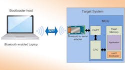
The baud rate of the Bluetooth module should match the baud rate configured in the target system’s bootloader. Most Bluetooth modules support AT commands to configure the baud rate of the modules using a USB-UART bridge or a microcontroller with a UART interface. The USB-Serial device part of the PSoC 4 Prototyping board can also be used to configure the baud rate of the Bluetooth modules using AT commands. The Bootloader host application tool can then use the Bluetooth virtual serial port to perform the bootload operation wirelessly. Figure 2 shows the system-level block diagram of the host and the target system.
If the bootloader host is another microcontroller, then wireless bootloading can still be performed with the help of an additional Bluetooth-to-serial adapter connected to the host microcontroller’s UART interface. For a PC without Bluetooth support, standard USB Bluetooth dongles can be used to establish a connection with the Bluetooth module.
Upon successful bootloading, the target system will start executing the new application. If another new application needs to be bootloaded, then the target system must be reset to start the bootloader again. This can be avoided by having the application call the bootloader. Then, the application that was bootloaded can respond to some external event, such as a button press or a particular data command received from the host, and start a bootload operation again to upload a new application on the target system.
Bluetooth Low Energy (BLE) modules can also be used for wireless bootloading. Unlike classic Bluetooth, there’s no SPP for BLE. However, in BLE, all of the profiles and service support is entirely in the application space. Product developers can develop their own serial-port service on top of the Generic Attribute Profile (GATT) in BLE modules and use it for wireless bootloading.
Bootloader Design Considerations
A robust bootloader should be able to detect, report, and gracefully handle errors that occur during the wireless bootloading, such as loss of packets during transmission, corrupted data, and flash write errors. Flash error checking is usually done by storing a checksum or cyclic redundancy code (CRC) for the application. When the bootload operation starts up, it clears these bits. And they will update if the application is downloaded and installed successfully.
However, say a power failure occurs during bootloading. Then at reset, the bootloader detects invalid check bits and does not pass control to the partially loaded application. Instead, it waits for the host to start another bootload operation.
Once a new application is bootloaded, the bootloader must validate the bootloadable image and then turn over control to the new application. A bootloader should also be able to check its own image in flash to see if it’s valid.
Another key consideration is to prevent the application from overwriting the bootloader itself. If the bootloader gets corrupted, or is overwritten by the application, then the system could become nonfunctional and would require that the bootloader be reprogrammed onto the system. To avoid this, the bootloader area in flash must be protected to prevent accidental overwrites of bootloader code.
Another important consideration in bootloader design is the timing to begin communication with the host. After determining that the application is valid, the bootloader can wait a certain amount of time for the host to start a new bootload operation. If the wait time is too short, the host may not be able to reliably start communication. If it’s too long, the product’s overall startup time may be too long. Similar to the solution for avoiding device reset to bootload a new application, the timing problem can also be solved by enabling the application to call the bootloader.
To make the target system fault-tolerant, one can use a Multi-App bootloader, which is able to store multiple application images in flash. If the bootloader detects that one of the application images is corrupted, the bootloader can jump to one of the other images. The number of applications that can be stored will depend on the size of the flash memory in the target system.
A bootloader can also include simple debug functionality, which would be implemented using a UART interface and a terminal emulator program like “Tera Term” to display the debug information in PC. Any debug information can also be sent wirelessly using the same Bluetooth-to-serial adapter.
Customizing the Bootloader Host Tool
Standard bootloader host tool applications are readily available for different microcontrollers. They can be used directly without any modification for wireless bootloading using SPP. However, the bootloader host tool could be customized to better suit wireless bootloading, and/or embed a terminal emulator window to view debug messages or even call the bootloader from the application by sending specific data wirelessly using SPP.
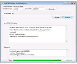
Figure 3 shows an example of a customized bootloader host tool application with an embedded terminal emulator window. To make full use of the terminal emulator, any new application bootloaded into the target system must also contain a UART interface and be able to call the bootloader when specific data is sent from the host to the target system. The bootloader and the application share the UART interface.
With a slightly sophisticated Multi-App bootloader design, it’s also possible to switch between multiple applications stored in flash by wirelessly sending different messages from the host to the target system using SPP. This will save the time required for bootloading a new application.
This file type includes high resolution graphics and schematics when applicable.
References:
Application Note AN73854 – PSoC 3, PSoC 4, and PSoC 5LP Introduction to Bootloaders
Application Note AN68272 – PSoC 3, PSoC 4, and PSoC 5LP UART Bootloader
About the Author
Varun Karthikeyan
Systems Engineer
Varun Karthikeyan is a Systems Engineer at Cypress Semiconductor with two years of industry experience in Embedded System Development. He completed his Bachelor of Engineering from P.E.S Institute of Technology, Bangalore, India.


