Carrier Aggregation: Implications for Mobile-Device RF Front-Ends
This file type includes high-resolution graphics and schematics when applicable.

Mobile-network operators need more capacity and faster speeds to meet the insatiable demand for mobile data while ensuring a good user experience, particularly for streaming video and other data-intensive applications. They need to offer higher-bandwidth services to acquire and retain customers. The challenge is to achieve these goals with spectrum that’s fragmented across multiple bands and varies between regions.
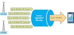
Carrier aggregation (CA) is the answer. The goal of CA is to enhance network performance and ensure a high-quality user experience by enabling operators to provide higher uplink and downlink data rates using their existing spectrum. CA is a feature of LTE-Advanced (first defined in 3GPP Release 10), enabling operators to combine multiple LTE component carriers (CCs), each up to 20 MHz wide, to create wider-bandwidth services.

Initial CA specifications allowed the aggregation of up to five CCs for a maximum of 100 MHz (Fig. 1). As for 3GPP Release 13, which is still under development, it includes plans to expand the number to 32 CCs. Over time, CA is expected to enable theoretical data rates of around 1 Gb/s.
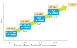
As for Initial CA deployments, only two CCs were aggregated for a maximum data rate of 300 Mb/s. However, more CCs are being added each year (Fig. 2). Faster speeds require more advanced modems in mobile devices; LTE Category 4 modems are required for 150 Mb/s, Category 6 for 300 Mb/s, and Category 9 for 450 Mb/s.
Types of Carrier Aggregation
To date, several operators have focused on implementing CA for downlink only (from network base station to smartphone), to meet the immediate user requirement for faster performance when using data-intensive applications such as streaming video, mapping, social media, and web browsing. However, there’s growing interest in uplink CA (from smartphone to base station) as consumers and businesses move to cloud computing and store more information online.
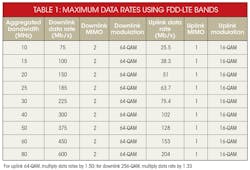
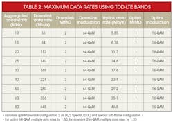
CA can use frequency-division duplex (FDD) LTE bands, in which uplink and downlink traffic use different frequencies, or time-division duplex (TDD) bands, in which uplink and downlink traffic share the same frequencies. Some new aggregation cases involve combining FDD and TDD. Due to the differences between FDD and TDD, the same amount of aggregated bandwidth results in different downlink and uplink data rates. Therefore, 40-MHz aggregated bandwidth in FDD-LTE results in a maximum downlink data rate of 300 Mb/s, while 40 MHz aggregated in TDD-LTE results in a maximum rate of 224 Mb/s (Tables 1 and 2).
Carrier aggregation supports different configurations of CCs. Intra-band contiguous CA uses multiple adjacent CCs within a single band, while intra-band non-contiguous CA employs multiple separated CCs within a single band. Inter-band CA combines multiple CCs that are spread across multiple bands. In some cases, inter-band CA combines widely separated bands, such as the aggregation of a high-frequency band (≥2300 MHz) with a low-frequency band (≤960 MHz). Other cases may involve aggregation of closely spaced bands, such as combinations of two or more mid-frequency bands (1428-2200 MHz). The various CC configurations present different problems for RF front-end designs.
RF Architecture Challenges
CA creates several new challenges for engineers working on RF front-end solutions in mobile devices. The difficulties include cross-isolation, which means avoiding interference between aggregated bands. In addition, solutions must continue to meet system requirements for in-band isolation between the transmit and receive frequencies of each band. While meeting these isolation requirements, designs must also minimize insertion loss to maintain competitive system sensitivity and optimize power consumption.
Solving Downlink CA Challenges
With downlink CA, the phone receives on two or more bands and transmits on a single band. The simultaneous reception on multiple bands creates a higher probability of interference. The interference challenges are increased by the fact that many smartphones now use multiple antennas to support low-band, mid-band, and high-band frequency coverage. An architecture might employ two primary and two diversity/MIMO antennas, which limits the physical space between the antennas and results in poor isolation between them. The challenge is to ensure cross-isolation and in-band isolation on both the primary and diversity Rx chains.
Issues with harmonic frequencies are one of the first problems encountered when aggregating widely separated bands to support downlink CA. Harmonics are generated at multiples of the transmitted band frequency by nonlinear components in the RF chain, including power amplifiers (PAs), switches, and even filters and duplexers. This creates isolation issues with certain band combinations, in which a harmonic of the lower-frequency band falls into the Rx frequency range of the higher-frequency band. Examples are B4+B17, B3+B8, and B1+B26.
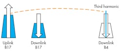
To illustrate the problem, consider the case of downlink CA using B4+B17, with a device transmitting on B17 and receiving simultaneously on both B17 and B4. The B17 Tx frequency range is 704-716 MHz, so the third harmonic of the TX signal (at 3x the Tx frequency) falls directly into the B4 Rx frequency range (2110-2155 MHz) (Fig. 3).
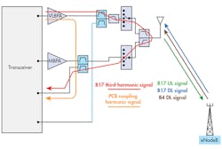
The problem is that if the B17 3x harmonic signal is not sufficiently attenuated, it can feed into the B4 Rx path and desensitize the smartphone’s primary receiver, effectively reducing operator network coverage. The harmonic signal may also be picked up by the phone’s diversity receive antenna, desensitizing the diversity receiver. Figure 4 represents a simplified RF front-end, showing the individual signal pathways of the harmonic interference.
To prevent interference, the filters in the RF front-end must provide very high rejection of the problem harmonics, without adding unacceptable loss that compromises the ability to meet the system link budgets. These requirements apply to the duplexers or bandpass filters used for each of the Tx and Rx frequencies, as well as diplexers. In addition, high linearity is required in all components, including PAs, PA/duplexers (PADs), switches, and filters, to minimize the generation of harmonics. Typically, mobile-device designers target harmonic isolations of ~90 dB or greater between PA outputs and receiver inputs.
A different cross-isolation challenge occurs with aggregations of closely separated bands, such as B2+B4. In these cases, the Tx frequency of one band is close to the Rx frequency of the other aggregated band. The challenge is to allow simultaneous use of both bands, but avoid the problem of the Tx signal of Band A desensitizing Rx on Band B.
Multiplexers can provide a highly efficient and elegant solution to the challenges of aggregating closely spaced bands, while also saving board space. A multiplexer includes the Tx and Rx bandpass filters for all of the aggregated bands, allowing the aggregated bands to share the antenna while providing isolation and cross-isolation for each band.
To achieve cross- and in-band isolations with low insertion loss, multiplexers are carefully designed by combining complementary matching individual Tx and Rx filters. The benefits of multiplexers are printed-circuit-board (PCB) space savings, simplified system design, and lower loss than alternative approaches. These are big advantages over using multiple duplexers, switches, and phase shifters to allow concurrent multi-band operation.
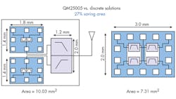
For example, the Qorvo QM25005 B1+B3 quadplexer provides high cross-isolation and in-band isolation that improve system sensitivity for better reception, together with lower current consumption than an alternative duplexer design approach (Fig. 5). The multiplexer achieves about a 27% space savings compared with discrete components.

Addressing Uplink CA Challenges
While early CA deployments have been solely downlink, uplink CA is beginning to gain interests from businesses and consumers due to several market drivers, including cloud computing. China is the first market to prioritize commercialization of solutions, initially focused on the TDD-LTE bands used extensively in that country. Increasing uplink performance is particularly important for TDD-LTE because each band’s uplink data rates are limited by the fact that the same frequencies are used for uplink and downlink, with most capacity allocated to downlink.
Intra-band aggregations may be among the first uplink CA implementations since they’re the easiest to implement. However, because intra-band CA involves the transmission of wideband signals with high peak-to-average ratios, it will require PAs with very high linearity. Envelope trackers will also need wider bandwidth capability to support these signals.
Uplink CA also creates several interference challenges that will need to be resolved. With inter-band uplink CA, interaction between the signals transmitted on different bands can create intermodulation frequencies that falls into Rx bands or auxiliary bands used for other purposes such as Global Positioning System (GPS). Intermodulation products can also be created in intra-band uplink CA via non-contiguous resource blocks.
CA represents a major advance in network performance with significant benefits for users and operators. It also presents new challenges for mobile RF front-end designs. Overcoming those challenges will require innovative high-performance solutions that ensure isolation between and within bands, while offering high linearity and low insertion loss to optimize network coverage and maximize smartphone battery life.
About the Author
Dennis Mahoney
Principal Engineer, Advanced Solutions Business Unit
Dennis Mahoney is a principal systems engineer in the Advanced Solutions Business Unit of Qorvo. Current responsibilities include managing an applications team and defining component specifications. Dennis has more than 15 years of experience in systems engineering and applications engineering positions, working on transceivers and RF front-end components. He has several patents related to transceiver architectures and calibrations. He received his BSEE and MSEE from Georgia Tech.
Comment About the Article
To join the conversation, and become an exclusive member of Electronic Design, create an account today!

Leaders relevant to this article: