The High Definition Multimedia Interface (HDMI) 1.4 specification supports cinema-quality video resolution of 2160p (3840 by 2160 pixels), also known as Quad HD, “4Kx2K,” or just “4K.” It also can support true 1080p 3D video at a 60-Hz refresh rate. The 2160p format allows for four times as many screen pixels as the ubiquitous 1080p TV format and runs at a data rate of 2.97 Gbits/s (also known as 3Gbps). Until recently, integrated silicon solutions for systems engineers to design 2160p and 1080p 3D 60-Hz video systems have not been available.
Applications for 3Gbps HDMI solutions include audio/video receiver (AVR) boxes, video wall displays, switchers, extenders, 4K projectors, and 1080p60 3D video generation. As the insatiable demand for video resolution continues to increase, more 3Gbps applications will come to market. 3Gbps HDMI interface solutions provide new features to the video space that were not previously available in past versions of the HDMI specification.
The Design Challenges
Even with the best silicon solutions, smart layouts and attention to printed-circuit board (PCB) challenges are needed to prevent bit errors in a 3Gbps video system. The fast data rate requirements of the latest video resolutions are pushing the limits of physics on the standard FR4 PCB material. Although higher-performance board trace materials are available, they may not be practical in a consumer electronics application due to their higher cost compared to FR4. But with careful attention to layout detail, a 3Gpbs HDMI system solution using FR4 can still be attained.
Three important board layout issues could arise with a 3Gbps HDMI signal resulting in system failure. The first is poor transition-minimized differential signaling (TMDS) intra-pair matching and poor termination (see “What Is TDMS?” below). Next is the capability to recover HDMI data in spite of attenuation loss on cables and FR4 board material. Finally, crosstalk with other noisy signals can cause inter-symbol interference (ISI). Any one or all of these issues could degrade the video signal enough to be inoperable in the system.
With a data period of only 336.7 ps, the timing skew relation between all of the HDMI signal paths must be closely watched during system board design. Each TMDS signal pair should be routed as close together as possible to keep the trace lengths within the pair matched and to maintain 100-Ω differential impedance along the entire transmission line. In addition, each of the three pairs of traces should be kept the same length to minimize the inter-channel mismatch at the HDMI receiver chip.
Care should be taken to avoid routing the TMDS data signals adjacent to or over other digital communications and clocks, such as the Display Data Channel (DDC) interface or the Consumer Electronics Control (CEC) control lines. Such routing could induce unwanted crosstalk to couple onto the TMDS signals, causing bit errors.
Due to the permittivity of commonly used FR4 material of 0.45 to 0.48, –1-dB signal attenuation can be seen for approximately every 8 inches of total trace length within the HDMI transmission line. All other passive electrostatic discharge (ESD) protection devices and connectors will further increase the attenuation of the signals and further distort the impedance matching. Although higher-performance PCB materials are available to the designer, they may be cost prohibitive for high-volume consumer electronics applications. To pass HDMI physical-layer (PHY) compliance testing at 3Gbps, the attenuation on the TMDS signals must be minimized to meet both Tx and Rx system requirements.
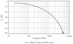
The HDMI cable typically acts as the largest component of signal attenuation within a video system. The magnitude of attenuation over an HDMI cable largely will depend upon its length and the quality of the wire gauge used. For example, a 30-meter 24 American Wire Gauge (24AWG) cable will attenuate a 2.97-Gbit/s (1485-MHz) signal significantly (Fig. 1). The signal at the far end of the 30-meter cable will be seen as –28 dB relative to the power at the beginning of the cable.
1. This plot shows the attenuation of a signal over a 30-meter HDMI 24AWG cable. Note the low pass roll off, particularly at 1485 MHz (3Gbps).
In absolute terms, this means that a 500-mV HDMI signal at one end will arrive as a 22-mV signal at the other end, not to mention the ISI distortion produced by the low pass effects of the cable. Since the cable quality and length used by the consumer will be unknown, it could be very difficult to continue to process this video signal without the system designer’s careful attention to board layout.
While most recently released HDMI receivers have integrated input equalizers, the performance of this circuitry plays an important role in the quality and capabilities of the overall HDMI receiver interface. Receiver equalizer adaptation in many cases can be user selected, based on cable length or video speed, whereby a static setting determines the best performance for the specific setup. However, a better alternative is a completely auto-adaptive equalizer that adjusts for all possible supported cable and frequency formats. Auto-adaptive equalization works best when the receiver can internally support both multi-frequency gain and boost.
The system designer must pay attention to the signal attenuation within a video system using 3Gbps video. Proper layout and trace minimization is needed to prevent bit errors on a 3Gbps HDMI signal path within a system. Unless higher-performance/higher-cost PCB materials are specified, standard FR4 material will significantly degrade the 3Gbps TMDS signal per unit length.
A typical home entertainment setup, office conference room, or theatre venue displaying 4K content may have a projector mounted on the ceiling. The system usually requires a relatively long HDMI cable length of anywhere from 15 meters (45 feet) to 30 meters (90 feet) from the source to the projector on the ceiling. This application is the most challenging for HDMI receivers, which will require the highest-performance auto-adaptive equalizer to maintain the quality and integrity of the signal being transmitted on a vast number of setup combinations that could be encountered. Examples may include a wide variety of HDMI cable qualities, cable lengths, and HDMI source transmitter performance differences.
To put the quality of the required equalizer needed in perspective, let’s look at the signal integrity of 4K content over several HDMI cable qualities and lengths. Currently, the most prevalent devices in the market used in displaying 4K content are projectors. 4K projectors currently have a significant cost advantage over an LCD or plasma TV showing 4K content.
The medical industry has adopted 8M pixel monitors as the next video standard to display ultra-high-resolution diagnostic images for doctors and medical professionals. However, the current implementation requires multiple Digital Visual Interface (DVI) interface cables to the monitor to provide the full video bandwidth to the display. Projectors that support 4K video content are bringing a new level of experience to the entertainment world due to their high-resolution content. This increase in performance and quality also brings along a number of technical challenges for HDMI receivers.
Measuring Transport Effectiveness
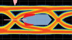
The quality and integrity of a 4K HDMI signal can be observed by looking at its data eye pattern at the far end of several different HDMI cable lengths transmitting 4K content at 3Gbps. The data eye pattern is a cumulative overlay of many samples of serial digital data transitioning from one to zero, creating an eye diagram over time. The eye diagram is a useful visual evaluation tool because it allows an understanding of how well the receiver will recover data without errors.
2. This eye diagram shows the 4K content at the end of a 30-cm HDMI cable. We can see the data eye already closing down, even on a relatively short cable.
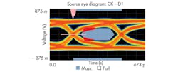
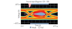
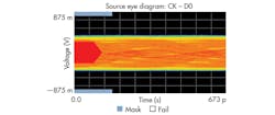
Typically, the best time to sample each transition, to guarantee error free transmission, is at the center of the open eye. An eye that appears closed minimizes or eliminates the potential to recover the data correctly. Figure 2 shows the eye pattern of 4K data content at the far end of only 30 cm of HDMI cable. The overlay of many samples for this configuration shows a fairly open eye, indicating that receiving errors are unlikely. At just 2 meters of HDMI cable length, we start to see a significant closing of the data eye at 3Gbps data rates (Fig. 3). As cable length increases, for the same data rate, the data eye performance diminishes significantly.
3. Here is another eye diagram showing the 4K at the end of a 2-meter HDMI cable. There is significant compromise of the data eye using a 2-meter cable, which is typically impractical for a projector application.
A phenomenon known as skin effect primarily limits most transmission lines used for high-speed digital transmission. The ability of free electrons to travel through the entire area of the conductor is reduced as the electrons are pushed to the outer edges of the conductor as frequency increases due to self-induced eddy currents. The depth at which the electrons are bounded to travel, from the outer of the conductor toward the center, is the skin depth.1
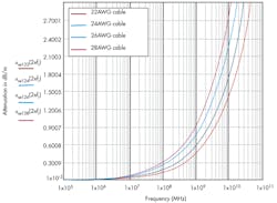
The smaller the diameter of the cable, the greater the attenuation is compared to cables with larger diameters (Fig. 4). This is important to know because the wire gauge of the HDMI cable and the performance of the equalizer on the HDMI receiver are the primary variables in getting the best performance out of an HDMI cable. The larger diameter conductor (lower AWG) in conjunction with the best performing equalizer will support the longest error-free transmission distance for 4K content.
4. This plot details the attenuation versus frequency of the signal per meter of cable with curves for 22AWG, 24AWG, 26AWG, and 28AWG wire. We can see that the cable AWG has a direct impact on the attenuation.
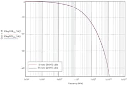
For a perspective of the channel loss and data rates supported on HDMI cables with different wire gauges, Figure 5 shows the transfer function of two HDMI cables with twice the length. A 22AWG copper cable is twice the diameter of a 28AWG cable. An HDMI cable that’s 15 meters long with 28AWG has exactly the same bandwidth performance as a 30-meter, 22AWG cable. Hence, both wire gauge diameter and wire length determine the bandwidth performance impact on the signal integrity at the far end of the HDMI cable.
5. The plot shows the bandwidth of two HDMI cables of different lengths but different wire AWG. We can now see that both cable length and AWG can impact the signal quality and each can be a tradeoff.
How Equalization Helps
The equalizer is one of the most important functional circuit blocks on an HDMI receiver. Without it, a consumer would not be able to deliver 4K video content over an HDMI cable longer than 5 meters. Not only is an equalizer important, but an equalizer that is fully adaptive to the attenuation produced by any HDMI cable is the best equalizer a consumer can use for every possible setup. It automatically selects the amount of gain needed for the given loss on the HDMI cable used. The main purpose of a fully adaptive equalizer is to “undo” the bandwidth limitations introduced by the skin effect of the copper in the cable at high data rates on different HDMI cable lengths and wire gauges.
Limitation on bandwidth produces a distortion on the signal eye known as inter-symbol interference (ISI). The bandwidth limitation produced on the HDMI cable acts as a filter on the transmitted signal, changing its shape and position relative to the adjacent symbol period at the receiver side. The result of this filtering causes a smearing on subsequent data periods, producing a closed data eye at the receiver.
Figure 6 shows this phenomenon with 3Gbps data content at the end of a 10-meter HDMI cable. In this case, the eye practically ceases to exist because the bandwidth-limiting characteristics produced by the HDMI cable are inducing ISI jitter. In turn, the periodic symbols shift and interfere with one another, closing the eye diagram. Without an equalizer in this case, there is essentially no way to be able to sample and recover the HDMI data correctly.
6. This closed eye diagram shows a 4K signal at the end of 10-meter HDMI cable, a typical length used in a projector application. This setup would require a receiver equalizer to correctly recover the data.
The equalizer reduces the low pass filtering effects of the HDMI cable, minimizing the effects of ISI jitter on the data symbols. A fully auto-adaptive equalizer assesses the amount of channel loss on the HDMI cable and adjusts different gain settings respectively to compensate for the loss automatically, without requiring system firmware to statically adjust for each cable and video format.
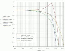
The main purpose of the equalizer is to minimize the effects of a 10-meter HDMI cable and make the signal appear like it was sent down a 5-meter or shorter HDMI cable by reducing the ISI jitter effects created originally by the additional signal loss on the cable. This can be seen in Figure 7. The signal in red represents a typical EQ transfer function gain selected by the fully adaptive equalizer to be applied to the 10-meter 28AWG HDMI cable in blue. The resulting new signal, labeled as 10-meter equalized cable in light blue, represents the bandwidth of the 10-meter HDMI cable after it has been equalized. For comparison, the new equalized 10-meter HDMI cable has very similar bandwidth characteristics to the un-equalized, 5-meter, 28AWG HDMI able up to about 3.1 GHz, which is well within the frequency range of interest.
7. Equalization can have positive effects on longer cables, such as those 10 meters in length. The equalized 10-meter performance can be improved to resemble that of a shorter 5-meter cable without equalization.
The Analog Devices ADV7619 can be used to achieve receiver equalization (Fig. 8). This 3Gbps, two-input-port, HDMI receiver is equipped with an auto-adaptive equalizer capable of adapting to very short HDMI cables as well as 30-meter, 24AWG long HDMI cables while supporting 4K content. A typical 30-meter, 24AWG HDMI cable produces more than –27 dB of signal attenuation at 3Gbps.
8. The Analog Devices ADV7619 two-port HDMI receiver offers auto-adaptive equalization.
The ADV7619 can recover signal loss from the cable, reducing ISI jitter and opening up the eye for excellent data recovery. As a result, it was designed to support video systems where both long and short HDMI cables of varying quality could be used to deliver flawless 4K video content. It also supports the 2160p and 1080p 3D 60-Hz 3Gbps video formats. Since 4K or 2160p displays are not widely available yet, Analog Devices has developed the ADV7619 Evaluation Kit, which enables system designers to validate a portion of a 4K video frame while using a standard 1080p monitor.
Conclusion
3Gbps HDMI interface solutions provide new features to the video space that were not previously available in past versions of the HDMI specification. However, system designers must be aware of 3Gbps signal constraints to maximize system performance. The input equalizer performance on an HDMI receiver plays an important role in the capabilities of a 4K video system.
Attention must be given to signal attenuation for a video system using 3Gbps video to accommodate the wide array of HDMI cable quality and lengths that consumers may use. Proper layout and trace length minimization are needed to prevent bit errors on a 3Gbps HDMI signal path within a system. Unless higher-performance PCB materials are specified, standard FR4 material will have a degradation of the TMDS signal per unit length. New silicon solutions like the ADV7619 are now available to help system engineers develop next-generation 4K video systems.
Reference
1. Johnson, H., & Graham, M., High-Speed Signal Propagation Advanced Black Magic, Upper Saddle River: Prentice Hall, 2003.
Jeff Ugalde is a product engineer for the Digital Video Products Group at Analog Devices, Greensboro, N.C. He has worked for ADI since 2001 and has specialized in HDMI receivers, transmitters, and transceiver products. He earned his bachelor’s and master’s degrees in electronic engineering from the University of North Carolina at Charlotte. He can be reached at [email protected].
Ian Beavers is a staff engineer for the Digital Video Products Group at Analog Devices, Greensboro, N.C. He has worked for the company since 1999 and is a team leader for HDMI and other video interface products. He has over 15 years’ experience in the semiconductor industry. He has earned a bachelor’s degree in electrical engineering from North Carolina State University and an MBA from the University of North Carolina at Greensboro. He can be reached at [email protected].
Lie Dou is a product marketing manager for the Digital Video Products group at Analog Devices. He has been with ADI since 2003 and specializes in video and display products. He has a BS from Fudan University, China, and a PhD in physics from Wayne State University. He can be reached at [email protected].
What is TMDS?
Transition-minimized differential signaling (TDMS) is an interface and coding technique developed by Silicon Image Inc. It uses an advanced coding algorithm that reduces electromagnetic interference (EMI) over copper cable that permits longer cables and greater bit transfer reliability. It is widely used with DVI, DisplayPort, and HDMI interfaces for video and audio signal transport. TMDS uses four differential pair transmission lines for three data and one clock signals. In addition, TMDS converts the 8-bit signals into 10-bit codes that minimize the number of 0 to 1 transitions that, in turn, reduce RF emissions. The code also minimizes the dc average on the line. The low-voltage differential signaling (LVDS) lines minimize noise.
