Extend Point-to-Point SSI Protocol to Support Multipoint Communications
This file type includes high resolution graphics and schematics when applicable.
The Serial Synchronous Interface (SSI) protocol, which implements a point-to-point communication channel for digital data and signal interface with optical encoders, is used for transmission of absolute position information as differential data in serial format. Since the SSI protocol is intended only for point-to-point communication, the receiver electronics must have an Ethernet interface to broadcast the position information to multiple indicating units. This design provides a method to remove the limitations in SSI and use it for multipoint communication.
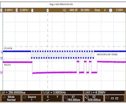
SSI uses a clock pulse train from a controller to initiate a differential serial output from the sensor. The number of clock pulses generated depends on the resolution of the encoder (both single-turn and multiturn types). Also, position data is continually updated by the sensor and made available to the receiving electronics. Between each clock pulse train, a minimum of 10 to 40 µs (monoflop time) is required by the sensor to load fresh position data into the sensor. When the sensor receives a pulse train from the controller, differential data (beginning with multiturn and single-turn position values) are subsequently shifted out (Fig. 1).
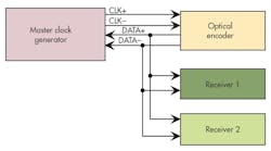
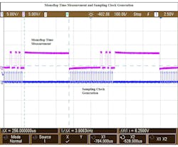
In the modified approach (Fig. 2), a master transmits the SSI clock to the encoder while multiple receivers receive the data from the encoder simultaneously. Since SSI is a synchronous protocol with the absence of start or stop bit, this simple design technique incorporates the data retrieval via observation of the monoflop time sequence, then generates the internal sampling clock that synchronizes with the incoming data (Fig. 3).
The master clock sends the synchronization clock to the encoder interleaved by the monoflop time, which is intentionally elongated to differentiate with the encoder's data transitions. The digital logic in the receiver electronics detects and measures the monoflop time period (MTP). Since encoder data follows the MTP, a sampling clock is generated after the falling edge of MTP and the data is stored in a serial-in/parallel-out shift register.
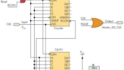
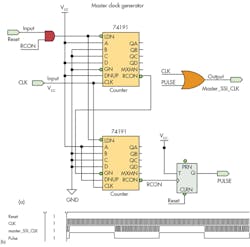
The master clock generator uses 13-bit single-turn and 12-bit multiturn absolute encoders (Fig. 4a). Its base frequency is 100 kHz with a MTP of 250 µs. The master clock generator uses cascaded 74191 4-bit synchronous counters, a T-flip flop, and an RS-485 transmitter (not shown). The counter is pre-loaded with a count of 25 (binary) corresponding to the resolution of the encoder (multiturn + single turn). Ripple carry out (RCON) is used to auto-load the counter and the T flip-flop output (PULSE) is ORed with main clock (100 kHz) to generate the desired SSI clock sequence. Figure 4b shows the simulated results.
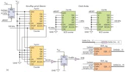
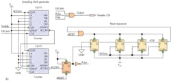
The receiver electronics comprise the monoflop period detector, sampling-clock generator logic, and a serial-in/parallel-out shift register (Figs. 5a and 5b). The monoflop period detector consists of cascaded 74191s configured as a down counter. If the duration is greater than 250 µs, the RCON enables the sampling clock generator circuit, whose output is fed to shift register. A microcontroller can be used to read the parallel data from the shift register and use it for local processing. A reset sequencer circuit is used to reset the shift register, so that it can acquire fresh data. (The simulated waveforms in Figure 5c can be compared to the experimental waveform in Figure 3.)
Note that redundant hot-standby, real-time, motion-control systems don’t use the SSI protocol, because the standby system is unable to decipher the position-data information due to absence of a synchronous clock. By using the approach shown here, it’s possible to effectively retrieve the position information on redundant systems, and thereby avoid the need to use more complex, higher-end encoder protocols such as Profibus or CANopen.
This file type includes high resolution graphics and schematics when applicable.
G.V.Kishore and K.Palanisami hold positions with the Power Electronics Section, Electronics & Instrumentation Division, Indira Gandhi Centre for Atomic Research (IGCAR), Kalpakkam-603102, Tamilnadu, India.
About the Author
G.V. Kishore
G.V. Kishore is with the Electronics & Instrumentation Division of the Indira Gandhi Center for Atomic Research, Kalpakkam, Tamilnadu, India.
K. Palanisami
K. Palanisami is with the Electronics & Instrumentation Division of the Indira Gandhi Center for Atomic Research, Kalpakka, Tamilnadu, India.
