Develop An Automotive RGB LED Interior Lighting System
Replacing ordinary incandescent lamps with LEDs for vehicle interior lighting paves the way for many customisation options. Apart from integrating light spots into the roof liner, light strips can be included in the decorative elements of the doors, door shelves, and beverage holders in the centre console.
Technical Requirements
A flexible concept is required to individually implement these lighting design options for different car models, car platforms, and OEMs. Standardised lighting nodes would contribute to a cost reduction without sacrificing the flexibility enabled by the programmability and the bus approach employed here.
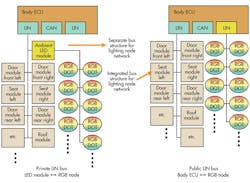
Thus, the hardware solution must include one LED per lighting node and enable flexible, bus-based connectivity and configuration options. The desired number of lighting nodes then can be flexibly selected according to the car’s configuration and controlled via the bus system. This approach is intended for systems ranging from a few to more than 20 lighting nodes (Fig. 1).
Each lighting node must feature on-board intelligence to meet all the requirements. As an additional key system requirement, it must be possible to replace the lighting nodes during a service call. Spare-part inventories also should be minimised to a single component usable for any lighting node. Finally, the ultimate cost level should make the entire application attractive for OEMs and end customers alike.
The lighting nodes must ensure that all LEDs operate at uniform brightness and colour. Aging and ambient-temperature effects affecting the LEDs must be compensated for. Furthermore, the interior lighting should not flicker or lose brightness when high-power loads are switched on. The brightness and colour of replacement LED nodes installed by a repair shop must be matched to the existing nodes to achieve a uniform appearance as well.
Technical Challenges
Based on the requirements of an ambient lighting system, RGB LEDs are employed due to their ability to emit different colours as well as pure white. The LEDs also must be able to be dimmed without affecting the colour of the light.
Generally, temperature does not affect the colour and brightness of the emitted light. LED production batches (bins) may have different colour characteristics. Additionally, LEDs are subject to aging. In other words, the luminous efficacy decreases over time.
To compensate for these effects, applications need an MCU that can be used for further tasks such as LIN communication along with the basic LED control functions. LIN is appropriate for this application because it is low-cost and easy to implement. It also boasts automatic node addressing (slave node position detection, or SNPD) and diagnosis functions.
Microcontroller
The MCU can be based on a 16- or 32-bit core (MSP430 or ARM-M0) with a clock frequency between 16 and 25 MHz. Between 16 and 32 kbytes of program memory are necessary for the software components including the LIN driver, temperature and aging compensation, brightness control, binning, and diagnosis.
By using a non-volatile EEPROM, individual correction parameters for binning can be stored for each node. In addition, a real-time counter recording the LED’s operating hours can be implemented for the aging-compensation feature.
A hardware-based LIN module or a UART interface accompanied by a LIN software driver is needed for LIN (slave) communication support with the main control unit’s LIN bus.
For controlling and compensating the brightness and colour of the LEDs, a timer with at least three outputs is required. Timing resolution should be better than 100 ns to compensate for colour variations even at low brightness levels. A fundamental pulse-width modulation (PWM) frequency of several hundred hertz should be used.
A 10-bit analog-to-digital converter (ADC) is beneficial to measure the LED’s forward voltage and to calculate its temperature based on the temperature dependence of its forward voltage. The ADC should be sufficiently fast to obtain adequate results even at low LED drive levels.
The MCU should support low-power modes because the network nodes may be connected to terminal 30, mandating ultra-low current drain of typically ≤10 to 50 µA per node.
LED Driver
A minimum of three LED drivers is required to control the red, green, and blue LEDs. Current sources with a rated maximum current of 20 to 30 mA are appropriate as LED drivers in ambient-lighting applications.
Total current will be much less than 30 mA in most cases because white light comprises red, blue, and green. Current will be highest for blue LEDs, which provide the lowest luminous efficacy.
Ideally, a constant current source should drive the LEDs to keep their brightness constant in case of voltage variations. A resolution of 5 bits is sufficient for a coarse pre-selection of the current level. In addition, the current source’s voltage drop should be minimized to support a minimum supply voltage of 6 V.
LIN Bus
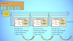
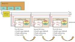
A LIN network can connect the LED nodes. For the future, the LIN nodes should be auto-addressable, enabling the assignment of a unique address to each LIN node when starting up the system. The single-wire daisy chain, bus shunt, and SNPD methods enable the assignment of a unique address to each LIN node following system startup (Fig. 2). Therefore, a single spare part can be used for any of the lighting nodes in the interior of the vehicle. The newly installed node will be initialised automatically.
The LIN bus also can be used for application control by sending dimming, brightness, and colour parameters to the nodes for a specific lighting mode. The diagnosis functions of the LED nodes can be implemented using the LIN bus as well.
Any LED failures or faults leading to node overheating can be reported to the central control unit, which can then record the event into the fault memory. The LIN driver will execute any safety measures itself, including node shutdown in case of overcurrent or overheating.
Power Supply
The power supply is implemented using a linear regulator meeting the requirements for operation on the vehicle’s 12-V electrical system. This includes the capability to withstand load dump events up to 42 V, jump starts up to 28 V, and continuous operation up to 18 V.
Overcurrent protection and overheating shutdown are standard features in automotive applications. The voltage regulator must also provide a reset signal for the MCU and a voltage monitoring feature, and its quiescent current should be low. While in sleep mode, the voltage regulator must supply power to the LIN transceiver, enabling the system to be awoken by a LIN bus event.
A dual-channel voltage regulator can be used consisting of two regulators in parallel, one of which supplies a current of 50 mA in the regular operating mode of the application. The LIN transceiver can wake up this voltage regulator in case of a bus event. The second voltage regulator supplies a very small current of a few microamps to the LIN transceiver’s wakeup circuitry.
System Integration
All the components required for this kind of system are available as discrete devices. Several options also exist for an integrated implementation. Considering the need for analogue devices including the voltage regulator, the LIN transceiver, the current sources, and the digital components (e.g. the MCU), a choice must be made between a complete system-on-chip (SoC) and a system-in-package (SiP).
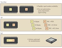
In a SIP solution, the MCU can be flexibly adapted to the memory requirements without affecting the analogue part, enabling multiple products to be offered with adequate memory granularity. Therefore, a variant featuring larger memory can be used during development and subsequently replaced by a memory-optimised version for cost reduction (Fig. 3).
Using a SoC for cost optimisation would make sense if the analogue and digital sections had an approximately equal share of the chip area. Drawbacks of this approach include fixed memory size and little flexibility.
The current sources driving the LEDs can be integrated into the analogue chip or the MCU. At first glance, the first option appears logical, although a couple of control and status signals must then be routed between both chips resulting in increased space, bond pad, and chip real estate requirements.
Instead, it is smarter to integrate the current sources into the MCU. This minimises the number of connections between the analogue and digital chips and contributes to the optimisation of the entire system.
Two potential problems arise because the system is intended for connection to the car’s battery voltage (terminal 30). First, the system’s total current consumption in sleep mode must be limited to a few microamps. Second, it is necessary to dissipate approximately 500 mW of power (heat) from the device under worst-case conditions. Due to the small size of the lighting nodes, their thermal resistance is considerable, resulting in poor heat dissipation. There are two ways to solve this problem.
First, replacing the linear regulator with a switching regulator could reduce power consumption, although this would raise the vehicle’s electromagnetic interference (EMI) level and lead to cost increases due to the additional external components needed by this approach.
Alternatively, we can utilise the fact that high ambient temperatures and high luminous intensity requirements are mutually exclusive. The interior of a car will heat up if exposed to sunlight, leading to high ambient temperatures. Yet the required light level will be low in this situation, enabling the current (and the power dissipation) to be limited.
A 20% to 30% reduction of the light output will not be apparent at full ambient brightness. Nonetheless, current and temperature levels should be monitored to avoid any device overheating. As the ultimate resort, the voltage regulator will limit the current.
System Solution
The following components can be used for the complete interior lighting control system:
• Section 1: A linear voltage regulator converting the battery voltage into the system voltage (including current-limiting and over-temperature protection)
• Section 2: A LIN driver supporting a LIN auto-addressing scheme
• Section 3: An MCU for computational tasks, LED driver control, network communication, and diagnosis functions
• Section 4: Three current sources driving the RGB LEDs, featuring temperature monitoring and over-current protection
Sections 1 and 2 could be integrated into one silicon chip, while an additional silicon chip could be made by integrating sections 3 and 4. It would thus be possible to draw maximum benefit from the advantages offered by the different process technologies optimized for analog and digital circuits.
An initial setup was built based on discrete components to implement the software for the LED control and compensation functions and for network-based diagnosis and programming.
An MSP430 available in many Q11-qualified versions (specifically, a MSP430FR5969 MCU with 64 kbytes of FRAM) was selected as the system’s MCU. This non-volatile FRAM can be read and written just like RAM.
As the memory content is preserved after switching off the supply voltage, FRAM can be used as code, data, and parameter memory. In contrast to conventional flash-based devices, there is no requirement for EEPROM emulation.
Supporting an almost unlimited number of write cycles, FRAM memory can be used to implement an operation-hour counter enabling an effective, aging-based LED brightness compensation scheme. The capacitive touch functionality provided by the MSP430FR5969 can be used for touch or proximity-based switch-on features.
An external resistor can be used to pre-select the current range provided by the TL4242 LED current sources, which offer protection against over-current, over-temperature, and polarity reversal. For controlling the LED current, the device’s PWM input can be tied to the MCU’s PWM output.
It is possible to integrate the three current sources required for RGB LEDs into a single chip. The TPS92630 providing three integrated current sources is appropriate for this purpose.
The functionality of the SN65HVDA100-Q1 LIN transceiver can be integrated in a later phase. However, the external transistor used to implement the SNPD feature would then have to be included in the integrated solution.
The TPS54040Q1 voltage regulator converting the battery voltage of 12 V into the 5-V system voltage is protected against load dumps, withstanding voltage spikes up to 42 V. A current limiting feature and an extended temperature range are also available.
The entire circuit was built based on a development board that is appropriate for software development and functionality demonstration. The RGB LED driver concept, the brightness and color temperature compensation scheme for the RGB LEDs, and the LIN SNPD approach were all built and tested using this setup.
Ralf Eckhardt is a systems application engineer at Texas Instruments. He holds a seat on various technical committees at Texas Instruments and lectures on semiconductor applications in the automotive industry at the Fachhochschule Rhein Main. He has been working at Texas Instruments since 1988 and studied electrical engineering at the Fachhochschule Wiesbaden.
About the Author
Ralf Eckhardt
Systems Application Engineer
Ralf Eckhardt is a systems application engineer at Texas Instruments. He holds a seat on various technical committees at Texas Instruments and lectures on semiconductor applications in the automotive industry at the Fachhochschule Rhein Main. He has been working at Texas Instruments since 1988 and studied electrical engineering at the Fachhochschule Wiesbaden.


