Filter Modules Offer Bulit-In Transformers, Low-Pass Filters
In June 2006, the IEEE committee ratified the 10GBaseT specification (IEEE 802.3an) establishing the standard for running 10-Gbit/s data throughput over CAT6 or better unshielded twisted-pair copper cabling. This standard gave IC houses and original equipment manufacturers (OEMs) a low-cost alternative to fiber. Designers started to revisit the platforms they were using as they developed 10-Gbit/s solutions.
Clearly, a 10-Gbit (10G) system operates at 10 times the speed of its 1G predecessor and covers a wider frequency spectrum. Yet this transition from 1G to 10G is a challenge in itself. Factors such as heat and size have already been addressed, but there are other issues to consider. Designers cannot simply replace a 1G active output interface (AOI) module with a 10G module and expect everything to work.
A wider transmission bandwidth is required, necessitating the use of new components such as magnetics and silicon that can perform over a wider spectrum. New magnetic components are needed to maximize the performance gains of a 10G port.
For instance, as frequency increases with more complex coding schemes, parasitics such as leakage inductance and distributed capacitance, which affects insertion loss and return loss, may cause the 10G port to no longer meet the required performance standards. Those factors have to be adjusted in a 10G Ethernet solution.
THE INTERFERENCE CHALLENGE
Perhaps one of the biggest challenges in 10G today is the interference present in many data centers. Circuit boards in data centers require 10G because they must handle much higher data rates. Their frequency range stretches up to 500 MHz or 600 MHz.
The lowest band from cell phones operates near the same frequency range. The frequencies used by cell phones and two-way radios coincide with some of the frequencies used by 10G chips, creating unwanted interference.
For example, if a person is using a cell phone in a lab or in close proximity to the switch rack, the signal-to-noise ratio (SNR) goes so low that it causes erroneous data transmission. Two-way radios can cause such a spike that they create havoc far worse than that of cell phones.
The interference problem brought by these devices triggered such attention that 10G system and physical-layer (PHY) vendors began to look for ways to rectify the problem. Upon ratification of the standard, no one really knew of the system’s vulnerability to cell-phone interference.
One proposed remedy is to implement the use of low-pass filters. Nevertheless, it is easy to deploy and has proven to be useful thus far. Note that the main signal spectrum for 10G stops just slightly above 400 MHz. However, extra bandwidth is required for 10G to improve SNR. This is the reason for using a low-pass filter: to filter out cell-phone noise at greater than 800 MHz.
The low-pass filter sets the bandwidth desired for operation and limits or blocks interfering frequencies from other devices in the area. Although low-pass filters remedy the interference problem, they also create new challenges for circuit board design and magnetic components.
CONQUERING THE SOLUTION
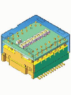
Magnetic modules (Fig. 1) that integrate a transformer and a low-pass filter within a single device offer significant advantages to designers of 10G systems. Once the transformer and filter combine with the PHY, it becomes a turnkey system for OEMs to create their switching systems and servers.
One major advantage of integrating the transformer and low-pass filter into one component is the superior performance, especially in relation to meeting key parameters such as return loss (S11) and insertion loss (S21). With less return loss, the signal can travel farther with little to no problem.
While it may seem that a perfect overall performance solution is achievable by putting a transformer next to a well-matched low-pass filter, in reality this is not the case. Putting them in close proximity helps with interference, but it does not ensure that the system can meet the return loss requirements caused by the interaction between them.
When the transformer and low-pass filter are in series, a signal has to pass through more components. Thus, there will be an increase in the number of traces potentially resulting in mismatched impedance and more parasitics that could further result in reduced performance. Parasitics differ on each board, and a small change in parasitics makes a big difference in a system’s performance. Traces must be short and the impedance requires perfect matching from beginning to end. Essentially, everything must balance well.
Another significant advantage of having one module that includes the transformer, choke, and low-pass filter is that they can be easily fine-tuned to work together. Generally, when the low-pass filter and/or the magnetics consist of discrete components, they must be fine-tuned after populating the board.
This causes a degree of difficulty because the interaction between discrete magnetics and filters is difficult to predict. But with the integration of the magnetic components, the transformers, and the filter, the end user won’t have to worry about such complexity, allowing for quicker design and the ability to use a package as a single device with more predictable behavior.
Also of note, when both parts are integrated within the same module, parasitics can be fine-tuned in advance, ensuring they are IEEE compliant. Fine-tuning can be accomplished with minimal changes, and the IC can be fine-tuned to each individual customer’s board with minimal modifications. It follows that having an integrated solution allows direct connection with the PHY, which reduces the traces and yields better performance.
Furthermore, for many IC manufacturers, each PHY must have a fixed value for low-pass filters. In the early stages of development, the PHY exhibits limited capabilities for implementing corrections. Standalone filters come with a set value, and there is no flexibility. Using a filter module with a built-in transformer and a low-pass filter offers flexibility because values are changeable when the system is fine-tuned.
Users can employ simulation software to determine the ultimate values required for the board while the manufacturer can measure the IC and test it again before board layout begins. Some systems need 5 Pole filters while others need 7 Pole. Therefore, new modules with integrated transformers and filters offer both pole options.
KEY CHANGES IN THE 10G ARENA
Since the inception of IEEE 802.3an, magnetics manufacturers have made significant strides in improving return loss on their transformers. First-generation 10G systems specified a return loss of –8 dB, and the second generation improved to –12 dB. Today’s 10G transformers (Fig. 2) packing highly tunable low-pass filters are performing at –20-dB levels at 400 MHz for discrete magnetics.
It is imperative to understand that some of the key parameters found in 10G differ from its predecessors. For example, inductance (OCL) has changed. In 100BaseTX Ethernet applications, a minimum of 350 µH of inductance is necessary. But in 10G Ethernet, there is no minimum inductance requirement.
Also, as transmit frequencies increase, it is important to be able to minimize noise. This is achievable by selecting good common-mode chokes in a discrete magnetics package and better shielding in an integrated package.
Switching to 10G Ethernet and using copper instead of fiber was very promising when the standard first went into effect because copper is one-third the cost of fiber. Although the overall power necessary to run fiber is higher than copper, the high 12-W per port range of the first-generation copper ICs set some limits on viable applications.
Now, the power wattage of a 10G copper PHY IC is at least 50% less. Some device manufacturers claim that newer PHYs consume only 3.5 W, making them an excellent fit for peripheral component interconnects. There is also less heat generation, which allows for the use of a smaller heatsink, making the chips viable for use in high-density, 48-port 10G switches.
FLEXIBLE DESIGN SOLUTIONS
ICs perform differently, depending on the magnetics. Some IC manufacturers have customers who prefer to have a choke first in the primary circuit and then the transformer, also known as a C+T configuration. Other manufacturers prefer the transformer and then the choke, a la T+C. Filter modules (Fig. 3) that include the transformers and filters can be used for either of these configurations.
When the low-pass filter and transformer are integrated together, it becomes apparent to the designer that any schematic configuration can be arranged and wires can be connected and/or reconnected in any design configuration deemed necessary by the IC manufacturer for the whole system. OEMs and device manufacturers can work with the magnetics manufacturer to customize the system configuration.
Yet another advantage for designers of these 10G systems is having the flexibility for device configuration and system design by having available to them a choice of filter modules that have the same overall footprint as the previous transformer modules, but also incorporate the low-pass filter necessary for the design. This offers the designer greater placement options for the transformer on the circuit board. Now achieving the smaller size, the designer can improve board density or trim the board’s dimensions.
Accounting for all of these factors, the move to 10G has become easier and more viable. The new filter modules with built-in transformers and low-pass filters offer greater flexibility in system design with better performance and reliability. IC manufacturers and OEMs now have more options in using chokes, transformers, and magnetics in a variety of combinations, resulting in custom board designs that work best for each company’s application.
About the Author
Comment About the Article
To join the conversation, and become an exclusive member of Electronic Design, create an account today!

Leaders relevant to this article: