Programmable Low-Pass Filter Design Using A Digital Pot And FilterLab
A common requirement in dataacquisition system signal paths is a low-pass filter. This kind of filter is most often used to eliminate aliasing errors as the signal passes through the analog-to-digital converter (ADC). Usually, this type of circuit is implemented for each individual signal in the system with an operational amplifier, combined with fixed resistors and capacitors.
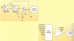
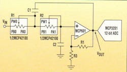
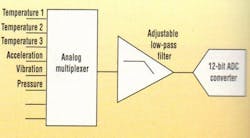
Figure 1 shows a programmable, second order, low-pass filter in a singlesupply, Sallen-Key configuration. As illustrated by Figure 2, this filter may be used for multiple signals. Also, it can reside on the ADC side of the analog multiplexer, instead of the multiplexer’s signal-source side. When this design approach is used, the number of required filters is dramatically reduced.
The filter in Figure 1 is implemented with four resistors and two capacitors. To create a programmable filter, two of the four fixed resistors in this circuit are replaced with a dual 100k, 8-bit digital potentiometer (MCP42100). The remaining two resistors are used to implement gain. If the desired gain of this circuit is equal to 1 V/V, R4 should be a short and R3 should be open. By adjusting the two digital potentiometers, the frequency cutoff of this secondorder low-pass filter can be adjusted across a 1:100 frequency range.
The design equation for the transfer function of the low-pass filter configuration can be seen in the equation box.
From this formula, it is possible to calculate the appropriate resistance values of the digital filter. Once these numbers are ascertained, the two capacitors can be carefully chosen as constants using iteration. Throughout this process, the digital potentiometer resistances are the only values that change.
An alternative to this tedious design exercise is determining the capacitor and resistor values using the FilterLab active filter design tool. (This free software program can be downloaded from Microchip Technology’s web site at www.microchip.com/10/Tools/Analog/fLab/index.htm.) The “circuit” screen in this program allows the user to adjust the capacitors to desired values. When these capacitors are set, the resistors in the circuit are changed to appropriate values for the circuit implementation.
For example, a programmable second-order, low-pass Butterworth filter with a corner frequency ranging from 200 Hz to 20 kHz can be designed by setting C1 = 0.022 µF and C2 = 0.1 µF. The values for this filter design as calculated using the FilterLab tool are summarized in Table 1. Also included in the table are the closest values for R1 and R2 from the digital potentiometer, along with the digital program code for the MCP42100.
Ideal filter performance can be verified by using the Spice listing that the FilterLab program provides as an output. If the capacitors used maintain 20% accuracy, they will dominate the filter’s part-to-part variability in a manufacturing environment (Equation 1).


