When a microprocessor stops responding, the typical remedy is to initiate a system reset. This led to the creation of the reset IC—a device that’s become an essential component throughout the computing industry over the past 15 years.
The reset function can be implemented in software, but it often remains a standalone device, running from its own power supply and separated from the microprocessor or PMIC. New challenges emerge, though, in the increasingly mobile computing environment. They revolve around allowing a user to easily reset the microprocessor or PMIC, and not having users accidentally initiate a reset while performing some other task.
Historically, cell-phone design includes removable batteries, wherein the user simply removes the battery to initiate a system reset. More vendors are moving to enclosed batteries, though, because it often enables the use of a larger battery, extending smartphone or tablet operating time before the need to recharge.
Related Articles
• Dual-Input Power Reset Stops Automotive Software Runaway
• Answering the Call for "Smarter" Smartphones
• Reset Chips Enable Safe Restarts
An enclosed battery requires another method to initiate a system reset, though, which has shifted vendors in the direction of pushbutton reset ICs. Moreover, to prevent accidental resets, which could easily occur with a button on a cellphone, reset ICs were created with one or two pushbutton reset inputs that must be pushed for two to 12 seconds. The pushbutton reset ICs also provides a more sophisticated user experience than the cumbersome method of removing and replacing the phone’s battery.
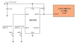
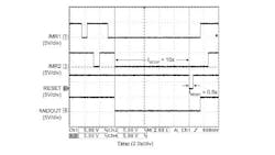
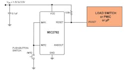
The most common application for pushbutton reset ICs uses the single, active-low, open-drain RESET output to assert a reset condition to the microprocessor, PMIC, or load switch (Fig. 1). This occurs after pushing pushbutton inputs for the setup period (tSETUP), typically in the range of two to 12 seconds. Figure 2 demonstrates both pushbutton inputs being asserted and the RESET output asserting for a fixed reset period (tRESET) of 0.5 seconds, after asserting both inputs for the tSETUP of 10 seconds.
Initiating “Soft” And “Hard” System Resets
Consumer product manufacturers typically must contend with the issue of accidental hard resets, namely how to eliminate them from happening. The best method is to use the aforementioned pushbutton reset IC. Intended for the safe generation of hard system resets, the dual inputs and long setup periods protect against accidental system resets in smartphones, tablets, eBooks, set-top boxes, personal-navigation and medical devices, and toys.
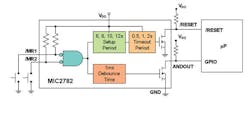
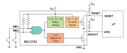
Another performance-enhancing feature, the de-bounced output (ANDOUT), asserts 1 ms after assertion of both /MR1 and /MR2. The ANDOUT output can be used to assert the /RESET input of a PMIC or microprocessor, which may have its own software-based “soft” reset routine.
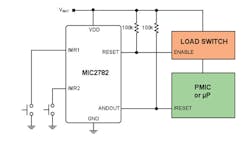
In such a scenario, the /RESET input would need to be asserted low for, say, eight seconds. If, after eight seconds, a software-based reset hasn’t been initiated and the user continues to hold the button for the 10-second setup time, then the RESET output will assert low to disconnect the load switch (placed between the battery and the PMIC and/or microprocessor). This would assure a hard system reset.
A “soft” software reset will typically take the system less time to reset than the “hard” system reset. That’s because the hard reset disconnects the battery, cutting power to the entire system (Fig. 3).
How Many Push-Button Inputs?
Currently, designers can choose from several different options for pushbutton reset ICs. Some vendors prefer two pushbutton inputs because they feel pushing both buttons simultaneously is the safest way to avoid accidental resets. Such a safeguard is perhaps most important for medical applications, where accidents can have life or death consequences.
However, the recent trend in smartphones and tablets seems to be shifting towards single-pushbutton input ICs with a long setup period. These, too, provide the necessary protection against accidental resets. A third option is a flexible two pushbutton input IC—it can be used with both inputs, or a single pushbutton input can be implemented by connecting both inputs (/MR1 and /MR2) (Fig. 4).
Setup/Reset Period Timing Options
As mentioned earlier, typical tSETUP timing options range from two to 12 seconds. Ideally, timing is factory-programmed or can be programmed through a three-state input. Other available solutions employ a capacitor to set the setup period, but adding such components obviously becomes an issue in space- and cost-constrained applications.
Upon assertion of a reset condition, the pushbutton reset IC will hold the reset condition for as long as the pushbutton inputs are asserted. It also can be asserted for a fixed reset period. A fixed reset is desirable because it prevents excessive current draw through the open-drain output, which otherwise could drain the battery should the reset condition be inadvertently asserted for a long time.
Reducing Production Test Time
Production testing a device with a two-to-12-second setup can take considerable time on the production line. Conversely, the production testing of this feature could be eliminated altogether if production testing proves too time-consuming. One solution is to use an ANDOUT feature, which responds 1 ms after assertion of both pushbutton inputs to drive an unused I/O port (Fig 5).
Output Options
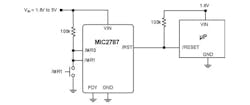
Most microprocessors and supervisors respond to an active-low input. The active-low open-drain output allows multiple outputs to be OR’ed together. In addition, it enables the supervisor to be powered from a 3.3-V supply, and the output level translated so that it interfaces to a microprocessor powered from a 1.8-V supply (Fig. 6).
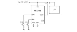
Another solution involves an active-high push-pull output that allows the pushbutton reset IC to drive a PFET load disconnect switch (Fig. 7).
To summarize, ever-increasing system and software complexity among mobile devices heightens the probability of a frozen, unresponsive system. Consequently, demands for a solution are growing louder—specifically, for a method that offers a system reset and prevents unintentional resets. Enter the dual-input pushbutton reset IC, which can provide answers to both issues, as well as meet size specs for mobile-device design. Dual-input pushbutton reset ICs come in sizes as small as 0.8 by 1.2 mm in CSP packaging.
Warren Hauff is senior product marketing manager for Micrel.
