The Ultimate Test Drive: High-Octane Oscilloscopes
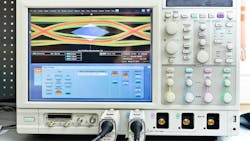
Most electronic engineers use an oscilloscope, so they know what they are, how they work, and how to apply them (Fig. 1). Right? Well, sort of. Most of today's scopes are digital storage (or sampling) oscilloscopes (DSOs), which tend to be rather complex and sophisticated animals. Generally speaking, you needn't know how something works to use it effectively. DSOs are a different case, though. The more you understand how these devices work, as well as their specs and limitations, the better you'll be able to apply their awesome analysis capabilities.
DSO Innards
Digital oscilloscopes really are just specialized versions of what almost all other electronic products are today—an embedded controller with a large memory, an LCD screen, and a super-fast analog-to-digital converter (ADC) (Fig. 2).
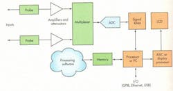
Today's DSO is a set of amplifiers and attenuators at the front end along with a matching set of probes that take in the signal and scale it to be received by the ADC. The ADC can digitize at a rate up to 40 Gsamples/s. Most of these devices are 8-bit ADCs. The captured signal is then stored in a fast memory. A key specification is memory depth as expressed in megasamples.
A fast special processor or a dedicated PC runs a Pentium and the Windows operating system with its own memory. The big benchtops also contain an internal hard drive and multiple I/O-networking interfaces. The processor and its software perform the signal examination, analysis, and measurement. Finally, the signal is displayed on a large monochrome or color LCD thanks to an accompanying ASIC or another fast processor with its own display memory.
The key point is that the software drives the scope's performance. Once you capture the signal in RAM, you can store it on the hard drive or even on a USB thumb drive for later analysis, online or offline. It can even include some elements of logic and protocol analysis.
The modern DSO is a cool piece of technology out on the leading edge, which also happens to be very expensive. But just remember to calculate the return on investment on a scope. Newer and more powerful models can really improve your productivity by saving you time and aggravation on your project— but only if you have the right scope for your needs.
What Scope is Right for You?
While most scopes are general-purpose instruments, some are better for specific applications than others. Not only that, many scopes can be upgraded and supplemented with software-analysis packages that better fit what you're doing. Scopes vary widely, so when considering a new scope, you need to evaluate your choices carefully.
At the low end of scopes reside handheld portables for field service work. Coming in at the high end are huge, powerful, general-purpose benchtop scopes—some of which cost more than $100,000. In between those two extremes lie multiple midrange categories that include bench scopes as well as modular, virtual-instrument scopes.
Scope designs continue to evolve as the top manufacturers attempt to keep up with rapidly changing chips and applications. One great justification for a new scope would concern any work you might be doing on the latest high-speed serial I/O buses, such as PCI Express, Serial ATA, 10-Gigabit Ethernet, RapidIO, 1394a/b, Fibre Channel, InfiniBand, or FBD (fully buffered DIMM).
Slower serial interfaces like CAN, LIN, FlexRay, SPI, and I2C are exploding in designs everywhere, so your ability to test them is critical. RF and wireless work (like Ultra-Wideband measurements, timedomain reflectometry, and softwaredefined radio) is also growing, making new test instruments a necessity. Therefore, you should keep nine key features and specifications in mind when contemplating your next scope.
What Bandwidth Do You Need?
Of all the specs, bandwidth is the most crucial. Every scope exhibits a low-pass filter response that's a combination of the probes, input amplifiers, and other circuits before the ADC. The bandwidth is the upper 3 dB down cut-off frequency. You can find scopes with a bandwidth from about 40 MHz to well over 15 GHz.
Just remember that if you're looking at pulses and digital signals or complex modulation, you need a much higher bandwidth than the basic frequency of operation of the signals you will observe. Digital signals have fast rise and fall times and consist of a fundamental sine wave plus lots of harmonics.
If you want to see how a digital signal really looks, your scope needs to pass as many harmonics as possible. Generally speaking, a bandwidth at least five times the basic clock rate of the digital pulses is the minimum for digital signals. For analog signals, a bandwidth of two to three times the basic upper signal operating frequency is minimum. And don't forget that bandwidth is also related to the (10% to 90%) rise time by:
rise time = 0.35/bandwidth
For a bandwidth of 200 MHz, the shortest rise time that can be displayed is:
0.35/200 × 106 = 1.75 ns
If an input pulse has a faster rise time, the scope will only display its fastest rise time set by the bandwidth. Some scopes have a bandwidth/rise time relationship given by:
rise time = 0.4/bandwidth
rise time = 0.5/bandwidth
Be sure to check with the scope manufacturer's specs to see which applies and whether it is based on a 10% to 90% or 20% to 80% rise time.
Finally, with bandwidth, always give yourself some extra margin. The accuracy of your measurement depends on the bandwidth, so buy as much as you can afford. To be sure, double or triple what you calculate you'll need. And don't forget that clock rates, bus speeds, operating frequencies, and circuit responses continue to go up each year. If you want your scope to have a longer life, always buy the most bandwidth you can afford.
What About Sample Rate?
This is the second most important spec to get right. Sample rate is the ADC's speed of digitization. The bottom end is set by the Nyquist theorem, which says you need to sample at least as twice as fast as the highest frequency in the signal to be reconstructed.
The more samples you can get per cycle of any signal, the greater the resolution and the more closely the displayed signal will look like the actual signal. A general rule of thumb is to buy a scope with a sample rate that's three to four times the bandwidth, and as usual, add a little extra margin to be sure. You can buy scopes with sample rates well beyond 40 Gsamples/s.
Another good rule of thumb is:
Sample rate = 2.5 × bandwidth
If the sample rate is higher than this value, the scope can collect enough samples to reconstruct the waveform accurately in one pass using a single trigger.
A big problem called aliasing sometimes occurs when you try to look at a signal whose frequency is beyond the scope's sampling range. You will see a signal, but it will be at a frequency that's the difference between the sampling rate and the signal frequency. Following the above guideline generally solves the problem.
Keep in mind that most scopes only use one fast ADC. If you get two or more input channels, the sampling rate per channel will be divided by the number of channels. You can get the max on a single channel. But if you absolutely must observe two or more signals simultaneously, get a higher sampling rate.
SAMPLING MODES
Most scopes operate in what is called the real-time sampling (RTS) mode—that is, digitizing at the ADC's fastest clock rate. Other scopes also include a feature called equivalent-time sampling (ETS), where a signal is sampled repeatedly after being triggered at different times.
The scope collects more samples over several sampling periods to produce a greater amount of input-signal samples per cycle. This means you can look at signals that occur faster than a real-time sampling scope can digitize them. A slower ADC can provide good resolution, but at the expense of a longer acquisition time. The downside is that the signal must be repetitive for the ADC to sample it multiple times at different points.
And Then There is Resolution
Resolution is a measure of the dynamic range of the scope, and that in turn is directly related to the ADC's bit size. Most scopes use an 8-bit ADC, meaning the input range is divided up into 28 = 256 increments. The input amplifiers scale the input signals as needed.
This resolution works for most applications, though some that require a wider dynamic range also require a scope with 10 or 12 bits of resolution. The tradeoff is slower sampling speed to get that resolution.
Resolutions to 24 bits are available in scopes or digitizers that use a sigma-delta ADC. National Instruments' PXI-5922 digitizer module can deliver 500 ksamples/s at 24 bits, 10 Msamples/s at 18 bits, and 15 Msamples/s at 16 bits. It's good for audio, ultrasonic, and vibration measurements that demand greater dynamic range.
The Number of Inputs Matters
Most scopes offer two inputs, but you can get four if needed. Some special modular digitizers feature eight. You can cluster modular digitizers into a much larger number of inputs. The timing can be shared between them so all signals are properly phase-aligned. Some manufacturers provide an external accessory that will offer more digital inputs, but not analog.
Triggering is Important
Triggering is the ability to signal the beginning of an input capture, usually via hardware using amplitude, slope, or some other signal characteristic. The most common trigger targets are glitches and runts. Others include edge or width triggers. For highspeed serial data triggering, engineers seem to prefer specific serial pattern triggers. Very narrow (less than 300 ps) pulse triggers are also popular.
Once the scope acquires the waveform, software searches for specific qualities or conditions and flags them for more detailed inspection. In many scopes, the triggering is programmable using General-Purpose Interface Bus (GPIB) or LAN Extensions for Instrumentation (LXI) commands.
Memory is Key to DSOs
Memory is a measure of how many samples a scope can store. Typically, the greater the memory, the better—but that usually depends on the types of signals you're sampling. The faster the sampling rate, the faster the memory will fill up. Do the math.
Most scopes use fast SRAM or a combination of SRAM and DRAM, which makes for expensive memory. Memory ranges from about 16 Mbytes to over 1 Gbyte, and it's usually upgradable. But more memory isn't always a good thing; it depends on what you're doing. With less memory, less data will be captured, leading to faster processing. More memory could result in too much data and hours of analysis time.
Timing and Synchronication
If you need to use the scope with other instruments, look for a device with timing and synchronization capability. This lets you connect the scope to logic analyzers, signal generators, spectrum analyzers, or other devices to ensure precise triggering and measurements at the exact times.
Conventional Versus Modular Scopes
The conventional, familiar, generalpurpose benchtop unit can look at analog signals, digital pulses, or mixed signals in design and analysis. Or, you can use a modular or virtual instrument.
While the conventional benchtop unit has its own display and built-in PC, you can opt for a scope that comprises a modular digitizer connected to an external PC or laptop. The laptop provides the processing and memory options as well as the display. A modular unit based on the PXI standards can use the PCI or PCI Express bus internally to connect digitizers and other modules to form custom virtual test instruments (Fig. 3).
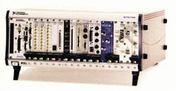
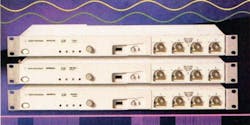
Modular instruments are far more common today, and the options from dozens of manufacturers make them attractive. You can build just the instrument you want or need and expand it later. Modular instruments are great for production and manufacturing test situations. You can even get scopes in modular rack form with no screen using the LXI standard, the Ethernet-based instrument connection standard designed to replace GPIB (Fig. 4).
Software is the Secret Sauce
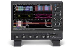
Software is the secret sauce of the modern oscilloscope. Pre-installed software analyzes the captured data to measure the amplitude, frequency, pulse width, rise/fall time, and other specs. These are displayed decimally on the screen along with the waveform. Special software packages are available to conduct far more detailed analysis of the signal (Fig. 5).
Some common analysis packages target jitter analysis, analysis of high-speed serial data streams including clock recovery and eye mask unfolding; Ethernet testing; power-supply (switching) analysis; DVI and HDMI; low-speed serial buses like CAN, LIN, I2C, and SPI; and memory testing (such as fully buffered DIMM and DDR2 compliance).
A fast Fourier transform option is an example that provides a frequency spectrum plot of the signal. Other software is for debugging. You can even program the scope yourself in some cases where your special needs can be met.
Always look for a scope that has good basic software to start. Some of this software can even be pre-installed. Also, choose your scopes from a manufacturer that continues to upgrade its products and offers additional analysis packages. Most manufacturers provide packages that let you generate user-defined functions generated by external software such as Matlab, LabVIEW, Excel, or other proprietary products.
Third-party software sources are growing, too. National Instruments' SignalExpress scope analysis software, designed for the company's PXI scopes, is also available for scopes from other companies like Tektronix. The SignalExpress signal analysis software is programmable in a drag-and-drop environment. Processing includes alignment, filtering, averaging, and scaling.
Measurements include amplitude, timing, and histogram in the time domain or power, frequency response, and distortion in the frequency domain. SignalExpress also allows sweep operations for limit testing. And, it can close the gap between design and test, which software providers have neglected up to this point. Analysis used during design can be more easily transferred to manufacturing test.
Another third-party software package for real-time scopes, Amherst Systems Associates' M1 OT (for oscilloscope tools), handles sophisticated analysis software tasks and more. Among the wide range of analysis features are RjDj jitter analysis and DDR2 compliance. It offers greater analysis precision as well as a TestScript feature that lets you program automated measurement sequences.
To help familiarize scope users with the analysis package, ASA's Cirrus Program gives away the M1 OT professional package (worth almost $8000) to any organization that is in the process of purchasing or has taken delivery within the last 30 days of a new Agilent or Yokogawa real-time scope. Check out ASA's Web site for more details.
The basic oscilloscope hardware has almost reached the commodity stage. New innovations will come from better software. Watch for more third-party software and stepped-up scope manufacturer software offerings.
For more, see "Jitter—A Scope's Toughest Challenge."
About the Author

Louis E. Frenzel
Click here to find more of Lou's articles on Electronic Design.
Comment About the Article
To join the conversation, and become an exclusive member of Electronic Design, create an account today!

Leaders relevant to this article: