
Many electronic design automation (EDA) solutions have evolved, which is not a bad thing. Evolution attempts to preserve the tools that are already in place—investments made by designers in languages, models, and general knowledge. Over time, those evolved solutions can become expensive to maintain, wasteful in terms of execution resources, or difficult to use for a new class of problems. Such is the case with functional verification.
Related Articles
- What's The Deal With SoC Verification?
- Surveying The Verification Landscape
- Sizing Up The Verification Problem
In the early days of constrained-random test-pattern generation, only data was randomized, so it was a fairly short hop from traditional directed testing. Before long, constraints had to be added to the inputs to ensure that only valid data sets were used. As more aspects of the test became randomizable, it became necessary to add functional coverage so the parts of the design covered by each test could be identified.
Early users of this technology were in the data communications field. Coverage based on simple observations was sufficient to identify ports on which data entered and exited, as well as the types of packets that moved through the system. But constraints as they had been defined only covered combinational behavior on the input data sets and could not deal with sequential behavior. Sequential constraints and sequences were created to get around this limitation.
Today, a hodgepodge of files and models are fed into verification tools, including the reference model, the constraint model, checkers, sequences and virtual sequences, and the coverage model. In many cases, there is redundancy among the models, and most are far from optimal. While companies perform most of their verification at the register transfer level (RTL), there is no compelling event to look at other solutions.
Mistakes or omissions made in any one of these models can result in the chip not being adequately verified or excess verification being performed unnecessarily. Many users report that the creation of the coverage model is one of the most difficult verification tasks. That’s due to the disconnect between what exists in a verification plan and the way in which that functionality can be detected through simple observations.
This file type includes high resolution graphics and schematics when applicable.
Challenges Ahead
When companies find that they need to perform verification at the system-on-chip (SoC) level, they discover an additional set of challenges. The first of these is simulator performance. While a simulator does not have a hard limit in terms of the design size that it can handle, performance degrades rapidly when it cannot fit the active areas of the design in cache. This is likely with full-chip simulation.
The second challenge is that the length of the tests that need to be run is increasing. Scenarios needed involve many discrete operations within the design, making performance issues even more acute. Third, many users report that the time spent in the testbench is equal to, or exceeds, the time spent in the simulator. As the length of the tests gets longer, the creation of useful tests will likely go down.
Finally, and probably most important, SoCs include embedded processors, and constrained-random simulation cannot deal with these design elements. They have to be removed and their buses turned into primary design inputs, making test creation even more difficult, forcing most companies to resort to directed testing for SoC-level functionality.
The Solutions
Given that the constrained-random approach cannot adequately address SoC verification, there’s an opportunity to redesign functional verification and to unify many aspects of a verification flow into a single coherent description. This description can be used on intellectual property (IP) blocks or a complete SoC, running on a system-level model, the RTL implementation, or any mix of the two.
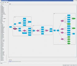
The mechanism to do this is a graph-based scenario model arranged so the roots of the graph are the functional goals (see “Surveying the Verification Landscape”).The figure illustrates how some aspects of this model work. An automated generator can “walk” this graph and generate multi-threaded, multi-processor, self-verifying C test cases to run on the SoC’s embedded processors and thoroughly verify its functionality.
The verification goal appears on the left in the figure. Two rectangles with rounded corners show two steps that must happen to fulfill that goal. They denote hierarchy and allow graph segments to be encapsulated and reused—for example, from the IP level to the SoC level. The top one, executed first, handles any necessary configuration. The lower one includes the action steps that need to be taken. Within the action steps, a diamond shape indicates to the test case generator that a choice can be made and the appropriate arc followed.
If the lower choice were made, the generator would make a further choice and perform another action. All arcs converge at the beginning of the next hierarchical action block, and again several choices are possible.
After working its way to the extreme right of the graph, the generator has all of the information necessary to create a test case. This includes the initial goal, the valid sequences of choices that can be made, the code that must be generated to run on the embedded processors, stimulus needed for the SoC’s inputs, and results checking needed on the SoC’s outputs.
The generated test case exercises a particular scenario or walks through the graph. Many test cases can be created easily to cover all the scenarios needed to verify the chip. Each additional test case walks through the graph again, making different decisions at the diamonds while randomizing data as well.
A graph-based scenario is more than this, however. Paths through the graph are also the system coverage model. At the first level of verification, the user may define that any path constitutes the goal as having been met. At the next level of verification detail, one might specify that each node, or perhaps each arc, must be used in a test case. It is also possible to specify sequences of arcs that should also be exercised.
To keep the generator within legal scenario space, the user can set constraints to allow data combinations or sequential dependencies. The user also can set biases. One choice should be made twice as often as the other, as an example. These constraints can be entered interactively and displayed directly on the graph.
The graph represents the functionality that should be present in the system and is independent of the architecture of the implementation being used to solve it. This requires a second description that defines what resources are available and how they are connected. The two descriptions are then fed into the test-case generator that will schedule the tasks that need to operate on the processors and to define the primary stimulus necessary.
When this phase of generation has been performed, the code is generated and the mechanism to synchronize the code with input events is created. No further time is spent on test-pattern generation during simulation, and it can be rerun any number of times without the extra overhead of the testbench generator. The code can be executed on models at any level of abstraction to drive a virtual prototype, an RTL simulation, or an emulator.
Conclusion
One model can be used to encapsulate an SoC design’s functionality, stimulus, results checking (possibly including assertions), coverage, and constraints. It can scale to the complexity of the system for which generation needs to happen and for the abstraction of the design being verified. In addition, separating the action of test-case generation from execution provides performance gains, particularly when a test case is run multiple times.
Adnan Hamid is cofounder and CEO of Breker Verification Systems. Prior to starting Breker in 2003, he worked at AMD as department manager of the System Logic Division. Previously, he served as a member of the consulting staff at AMD and Cadence Design Systems. He graduated from Princeton University with bachelor of science degrees in electrical engineering and computer science and holds an MBA from the McCombs School of Business at the University of Texas.
About the Author
Adnan Hamid
CEO
Adnan Hamid is the founder and chief executive officer of Breker Verification Systems, and inventor of its core technology. He has more than 20 years of experience in functional verification automation and is a pioneer in bringing to market the first commercially available solution for Portable Stimulus. Prior to Breker, Hamid managed AMD’s System Logic Division and led its verification group to create the first test case generator providing 100% coverage for an x86-class microprocessor. Hamid holds 12 patents in test case generation and synthesis. He received Bachelor of Science degrees in Electrical Engineering and Computer Science from Princeton University, and an MBA from the University of Texas at Austin.
Comment About the Article
To join the conversation, and become an exclusive member of Electronic Design, create an account today!

Leaders relevant to this article: