Unmanned Aerial System for Close-Range Filming Features Model-Based Design
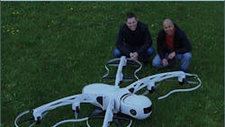
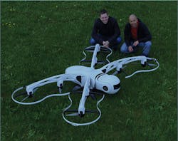
Airnamics’ R5 unmanned aerial system (UAS) provides cinematographers with a camera-motion system for close-range aerial filming. With a top speed of 130 kph (80 mph), a camera payload of 8 kg (18 lbs), and a GPS system accurate to within 25 millimeters (1 inch), the R5 is designed to deliver unprecedented levels of performance, safety, and ease of use.
This file type includes high resolution graphics and schematics when applicable.
Development of the R5’s fly-by-wire (FBW) controller and flight management system (FMS) was accelerated by using model-based design with MATLAB and Simulink.
“In flight-control-system performance, reliability and safety are primary concerns,” says Dr. Marko Thaler, CEO and CTO at Airnamics. “You cannot take shortcuts, because if you do, you’ll eventually crash. With model-based design, we were able to test the entire system via simulation. As a result, we not only sped the development and debugging of control algorithms, we also produced higher-quality code without expensive prototyping or long development cycles.”
The Challenge
Initially, the three-member Airnamics engineering team relied on handwritten C code. After several months of development, though, the approach was deemed too slow and inefficient. They lacked an easy way to run high-fidelity simulations using the handwritten code, which made debugging and quality-assurance activities difficult. As reliability and safety concerns mounted, the company looked for a new approach.
The engineers wanted to model the R5 aircraft and its control systems, and run simulations to verify and optimize the control algorithms. They also wanted to rapidly prototype the controller by generating code from the model and running the code on a real-time machine on the vehicle. Ultimately, the goal was to complete production versions of the software that could be certified by aviation authorities for real-world operation.
The Solution
Airnamics adopted model-based design with MATLAB and Simulink to accelerate development of FBW and FMS software for the R5 UAS. While Thaler already had substantial experience with MATLAB and Simulink, his two colleagues had only limited experience. To get up to speed, they used webinars and examples found on mathworks.com and consulted MathWorks application engineers.
Working with Simulink and basic components in Aerospace Blockset, the team created a plant model of the R5 aircraft, including the airframe, eight motors and propellers, three inertial measurement units (for redundancy and better gyro head stabilization performance), a laser range finder, and other sensors. In addition, the Simulink and Control System Toolbox made it possible to create a control model that included an attitude and motion-control algorithm plus an extended Kalman filter for state estimation.
Closed-loop simulations of the control model and plant model were run to verify controller functionality. As the design progressed, the engineers simulated sensor failures, motor failures, wind gusts, and other scenarios. During the simulations, Simulink 3D Animation was used to visualize the dynamic system behavior of the R5 aircraft.
In preparation for flight tests, Simulink Coder was utilized to generate code from the controller model, which was compiled and deployed to a custom-developed onboard PC with an Intel Atom processor running Simulink Real-Time. Following flight tests, the team analyzed flight-recorder data in MATLAB, and used the results to refine the plant model and optimize the controller. In some cases, development iterations were accelerated by updating the model and generating new code in the field between flights.
Airnamics is currently finalizing the R5 design and preparing it for certification. The company now offers a UAS development service that covers everything from conceptual design to serial production of custom-made UAS systems.
The Results
“With model-based design, our three-engineer team found more than 95% of control software bugs before the first flight,” says Airnamics’ Thaler. “We used the test flights to increase our Simulink models’ fidelity and isolate remaining bugs with high precision. The result is a safer, more reliable, and higher-quality product.”
Key advances include:
• Time-to-market shortened by up to an order of magnitude: “When developing a new UAS system from scratch, we’ve found that, for a small team like ours, model-based design can reduce the time to market and development cost by up to an order of magnitude compared with a traditional development approach with hand-coding,” says Thaler.
• Test flight anomalies quickly resolved: “A strong wind gust during flight testing resulted in unexpected behavior of the R5 control system,” says Thaler. “We used the flight-recorder data and Simulink to determine the direction and intensity of the gust, analyze the control algorithm’s response, and quickly pinpoint the part of algorithm that was not performing optimally.”
This file type includes high resolution graphics and schematics when applicable.
• Debugging time reduced from weeks to hours: “With Model-Based Design we have the ability to understand and reproduce errors in simulation instead of relying on flight tests alone,” notes Thaler. “As a result, in a matter of hours we can find and fix bugs that would previously have taken weeks to resolve.”
About the Author
Michael Vetsch
Product Marketing Manager
Michael Vetsch, product marketing manager for Real-Time Simulation and Testing at Mathworks, is a renowned expert on Simulink Real-Time (formerly known as xPC Target), having initially authored it in 1997. In prior roles, he was the MathWorks xPC Target development lead, and the founder and CTO of Speedgoat.


