USB Type-C: The Power Tool for Next-Generation Electronics
Download this article in .PDF format
Let’s face it, a new revision to an old standard isn't usually cause for wild celebration. But champagne corks were popping in August 2014 when it was announced that the USB Type-C connector standard was finalized. The new document took its place alongside its older siblings—the USB 3.1 interface specification and the USB Power Delivery specification (USB PD). Together they form a future roadmap for wired serial communications, and promise an exciting future for low-voltage power distribution, too.
What is USB Type-C, and why all the excitement?
The Road Less More Traveled
The Universal Serial Bus (USB) specification dates back to 1994, when a group of seven companies including Intel and Microsoft began initial development. The group now includes HP, Renesas, STMicroelectronics, Texas Instruments and others in addition to the original members. Together they comprise the USB Implementers Forum (USB-IF).
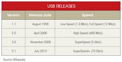
USB 1.1, introduced in 1998, was the first widely adopted version. The data-transfer rate has steadily increased over time (see table).
Before USB Type-C, USB receptacles and matching connectors came in two types (A and B) and three sizes. Only the type-A receptacle delivers power. The standard-size receptacle is commonly found on laptops and desktops. The "mini"-size version is popular on many cameras, while smartphones and tablets typically use the "micro" size.
“One Standard To Rule Them All?”
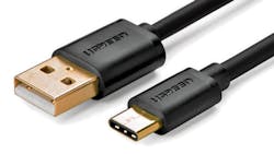
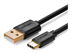
USB Type-C brings several important advances to USB interconnection. Figure 1 shows the old and new connectors. Although it's much thinner than Type-A (2.4 mm vs. 4.5 mm), Type-C contains 24 pins vs. only 5 in the older connector, which allows for a significant increase in performance and flexibility.
USB Type-C serves as a common standard for hosts (power sources) as well as receptacles (power users), replacing both Type-A and Type-B connectors. It's designed to be “future-proof,” with capability for future expansion. It also accommodates other standards with its Alternate Mode, discussed below.
What USB Type-C is.... and is Not
Strictly speaking, USB Type-C is a connector and cable specification. Since they're closely related, discussion of Type-C often includes features of the USB 3.1 and USB PD specifications, and that's how we'll talk about them here.
Because a product features USB Type-C, though, doesn't necessarily mean that it supports the other two specifications. A standard USB 2.0 system can still use the USB Type-C receptacle and cable without supporting either USB 3.1 or USB PD.
That makes sense. A flash drive, for example, may have a Type-A connector and only support USB 2.0, but it still needs to plug into a laptop's USB Type-C receptacle. Luckily, numerous adapter cables already exist to meet this need
USB Type-C Pinout
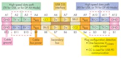
Figure 2 illustrates the USB Type-C pinout. It comprises five sections:
• Four VBUS/GND power and ground pairs
• High Speed Data Path: Four differential pairs for the USB 3.1 SuperSpeed mode, if implemented. SuperSpeed uses full-duplex communication.
• Two USB 2.0 D+/D– pairs: Required to implement USB 2.0 functionality (only one pair used)
• Two sideband pins: Available for Alternate Mode use
• Two CC plug configuration pins: Used to detect cable orientation and implement the USB Power Delivery specification
The USB Type-C connector is flippable because the pinout is rotationally symmetrical. The power pins VBUS and GND always match; reversing the connector connects the TX1 pair to TX2, the RX1 pair to RX2, and so on. The host device reads the voltages on the two CC pins to determine the connector orientation and changes the receptacle pinout accordingly.
Alternate Mode repurposes some of the pins in the USB Type-C cable for direct device-to-host transmission of non-USB data protocols. Alternate Mode transmissions use the four high-speed pins, two sideband (SBU) pins, and, for certain applications, the USB 2.0 pins and a CC pin. The modes are configured using vendor-defined messages (VDMs) through the CC pins.USB Type-C Alternate Mode
For example, DisplayPort is a popular interface standard for connecting a video source to a display device, such as a computer monitor. VESA, the USB-IF and DisplayPort's controlling authority, issued the “DisplayPort Alt Mode for USB Type-C Standard,” which governs its use over USB Type-C.
Under the standard, a USB Type-C system can carry native DisplayPort signals by repurposing up to four SuperSpeed pins (two TX/RX pairs). The Type-C secondary bus pins carry the DisplayPort AUX channel, which contains non-video data like audio or touchscreen information.
Future Alternate Mode implementations are expected to include HDMI, and even Ethernet.
The USB Power Delivery Specification
USB PD expands USB's power delivery options in several areas:
• It increases the voltage up to 20 V.
• It increases the power level to 100 W (20 V/5 A), enabling the use of devices such as USB-powered printers or HDDs.
• It allows power to flow in either direction; a device can potentially supply or receive power. In USB PD terminology, a port that supplies power is called a Downstream Facing Port (DFP); conversely, an Upstream Facing Port (UFP) receives power. A Dual Role Port (DRP) can perform either function.
• It adds real-time communication between devices. Devices negotiate with each other over the CC pins to determine the power flow in the system. Power roles can change dynamically, allowing a receptacle to become a host (source) and vice versa.
The USB Type-C Cable Specification
Although a USB Type-C system can accommodate a traditional straight-through cable (it uses default settings), complete implementation requires a full-featured USB Type-C cable—an active, electronically marked cable that contains a chip with a unique ID based on the configuration data channel and VDMs from the USB Power Delivery 2.0 specification. The cable’s active circuitry can draw maximum total power of 1 W.
For USB 3.1 applications, the high data rate effectively limits the cable length to one meter. The effective length for USB 3.0 is two meters.
In addition to the baseline 900 mA, USB Type-C devices also support power levels of 7.5 W (5 V/1.5 A) and 15 W (5 V/3.0 A). If they don't support the full USB PD specification, devices negotiate increased USB current through the configuration line.
USB Type-C System Design
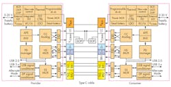
A full USB Type-C design is a complex undertaking. Figure 3 shows a sample block diagram; key parts include:
Power controller: A non-PD controller simply has to supply the specified voltage and power. However, a USB PD controller, consisting of the PD Manager, AFE/PHY, and CC Analog blocks, must carry out a complex series of operations.
First, it must detect when a cable is plugged into the Type-C connector and determine its orientation. Then it negotiates a USB PD power contract with the other device via the CC lines to determine the appropriate functionality and power levels using the USB PD bi-phase marked coding (BMC) and physical-layer (PHY) protocol.
Once negotiations are complete, the controller enables the appropriate power path and configures the Alternate Mode settings. At any time during operation, the contract may be renegotiated if conditions change. Therefore, the controller must respond to new inputs as appropriate.
HS MUX: The High Speed multiplexer switches the USB 2.0 D+/D– lines depending on cable orientation.
SS MUX: The SuperSpeed multiplexer routes the USB 3.1 lines depending on cable orientation, and accommodates repurposing of the TX/RX pins related to Alternate Mode.
Power-supply block: This block must deliver a wide range of voltages and current over the VBUS line to meet the various USB Type-C use cases. It contains multiple power-management blocks, including a programmable dc-dc converter, power multiplexer, linear LDO regulators, and protection against excessive temperature, voltage, and current.
Interface protection circuitry provides ESD protection and filtering to minimize interference.
Type-C cable: An electronically marked Type-C cable connects provider (DFP) and consumer (UFP); it contains the embedded devices as discussed earlier.
Single-Chip Solution
The full USB Type-C cost and complexity may not be necessary for many applications, since many low-cost Type-C systems only require USB 2.0 and a native Type-C power capability of 15 W. Examples include portables such as smartphones, phablets, tablets, and notebooks, and specialized applications like automotive infotainment.
Vendors offer one-chip solutions for these Type-C implementations. A typical device provides the configuration-channel (CC) logic needed for Type-C ecosystems; the CC pins determine port attach and detach, cable orientation, role detection, and port control for Type-C current mode.
Next-Gen Power Distribution
Once the full USB Type-C specification starts to become commonplace, exciting opportunities will arise to redesign dc power distribution for consumer devices. Eliminating the barrel power connector will allow tablets and notebooks to become thinner. Apple's Macbook has already eliminated multiple receptacles in favor of a USB Type-C port that's used with a Digital AV Multiport Adapter to allow HDMI and power connections simultaneously.
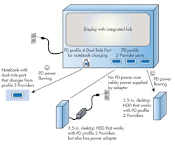
You can say goodbye to a bag full of wallwart power supplies every time you hit the road. In the new scheme, very few devices rely on a wall socket for power. Instead, integrated power hubs will route dc power to most devices (Fig. 4).
Here, the display receives ac power from a standard wall socket and includes a power hub that supplies dc power to multiple devices, each with their own DRP or UFP, depending on the device. In parallel with configuration and power data, normal USB serial data communication is also taking place.
In this figure, the hub contains a variety of receptacles, including a DRP that's charging a notebook. The hub provides power to an HDD, which also has its own power adapter and can supply power to the system if needed.
About the Author
Paul Pickering
Paul Pickering has over 35 years of engineering and marketing experience, including stints in automotive electronics, precision analog, power semiconductors, flight simulation and robotics. Originally from the North-East of England, he has lived and worked in Europe, the US, and Japan. He has a B.Sc. (Hons) in Physics & Electronics from Royal Holloway College, University of London, and has done graduate work at Tulsa University. In his spare time, he plays and teaches the guitar in the Phoenix, Ariz. area
Comment About the Article
To join the conversation, and become an exclusive member of Electronic Design, create an account today!

Leaders relevant to this article: