7 Good Reasons Why You Should Use Integrated Load Switches

Download this article in PDF format.
A load switch is simply a switch, mechanical or electronic, that connects or disconnects a load to the high side of a power source. A wall light switch is a load switch. Any off/on switch on an appliance or electronic product is a load switch. A relay can be a load switch.
However, a load switch is also a small electronic switch used in many products to configure and manage power distribution. You can make a load switch with discrete components, but there are significant advantages to using a fully integrated IC load switch. This article presents an option you may not know is available.
Load-Switch Concept
Figure 1 shows the simple idea of a load switch, where a power source provides a voltage to one or more loads. The switches are controlled by a microcontroller unit. The source is typically dc, but an ac source is possible. Different types of load switches are used for dc and ac—we will focus on dc load switches here.
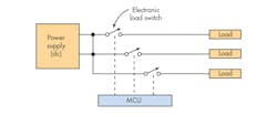
1. Load switches connect loads to a common power supply under the control of an embedded microcontroller unit.
Load switches are used to connect and disconnect a load from a source to power up or down, or to save energy when a load isn’t needed. They can also be used to sequence power off-on operations. These switches find homes in many products, including smartphones, tablets, laptops, digital cameras, watches and wearables, portable instruments, as well as other battery-operated devices.
How Load Switches Work
The most common type of dc load switch is a MOSFET (Fig. 2). This discrete-component switch employs a series P-type MOSFET and a gate-control MOSFET. The control transistor is usually driven by the GPIO output of a microcontroller.
Applying a positive logic level to the enable input (EN) turns on the lower MOSFET, which in turn grounds the series MOSFET gate and applies a forward gate-source voltage that turns on the series transistor. The capacitor controls the rise time of the output voltage to minimize the input voltage drop that occurs when the switch is turned on. Enhancement-mode MOSFETs are used to provide a low series on-resistance to minimize both voltage loss and power consumption.
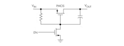
2. Here’s the basic circuit setup of a discrete-component load switch.
While discrete load-switch implementations work well, their main disadvantage is that they consume extra space on a PCB. The solution is a single IC load switch: Integrated load switches are a great way to reduce board space and improve switching performance and protection over existing discrete-component solutions.
Integrated Load Switches
Figure 3 illustrates a general block diagram of an IC load switch. Most manufacturers recommend input and output capacitors to minimize input voltage drop during the turn-on operation as well as provide extra output filtering.
The wide variety of models available offers a mix of different features. All load switches have the four basic connections: VIN, VOUT, EN, and GND. Some versions require an external BIAS voltage to operate some internal circuits. Other devices use an internal charge pump to deliver operational voltage for internal circuits. Some models also have a thermal-shutdown capability to control excessive power dissipation.
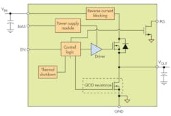
3. This general block diagram of a commercial load switch shows the core features.
Another feature is a power-good (PG) output that indicates when the output voltage exists at the output pin. It can be used to control other devices, such as additional load switches in a sequencing operation. One more feature, which isn’t included in some basic load switches, is reverse-current blocking. Many devices incorporate a quick-output-discharge (QOD) circuit that discharges the output when the device is turned off. When the enable input goes low, the logic turns on the lower MOSFET that discharges the external output capacitance.
To capsulize, here are seven good reasons why an integrated load switch is a better option than a discrete MOSFET solution:
- Saves space. A key advantage of the integrated device over discrete load switches is the small footprint. In compact products like a cell phone, space is limited and an integrated unit is more easily accommodated. Compare, for example, a typical discrete load switch that occupies about 17 square millimeters (mm2) to a common single-chip solution that uses only 4 mm2 .
- Simpler design. No discrete design time is required. Just buy the integrated chip and design it in to get all benefits and features.
- Quick output discharge. An internal resistance in the form of a conducting MOSFET is connected across the load. It serves to discharge to the output capacitor quickly when the enable input goes low.
- Reverse-current blocking. Some IC load switches implement a feature that blocks any reverse current. When the enable input goes low to turn off the switch, the reverse current block circuit is enabled thereby reducing any potential reverse current from output back to input to a very low level.
- Saves power. Using load switches to manage the power output of the supply minimizes power consumption, saves energy, and provides for longer battery life in portable applications. In its off state, the IC draws minimal quiescent current.
- Manages inrush current. This feature prevents input voltage droop that may transpire when the switch is first turned on. This is the result of a high inrush current that occurs when charging the output capacitor. Most load switches provide a controlled ramp up of the output voltage as it charges the output capacitor.
- Implements sequencing. Load switches let you implement the sequencing of loads during a turn-on or turn-off operation. Some designs with processors, FPGAs, and other chips require that different supply voltages be applied or disconnected in a specific order. Multiple load switches for each supply that are operated by the related embedded controller for timing meet this need. Certain load switches also feature an output signal that indicates when the output is fully turned on. This signal can be used in sequencing operations with other load switches in the system.
Figure 4 shows load sequencing without processor involvement. As the first output turns on, it enables the second load switch to turn on Load 2. Alternately, each load switch could be enabled by a separate GPIO from the control processor that provides the desired timing.
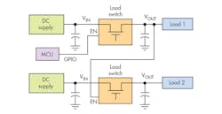
4. Load sequencing with load switches—as the first output turns on, it enables the second load switch to turn on Load 2.
Commercial Devices
Texas Instruments offers an extensive line of integrated load switches. The TP229xx series includes a variety of models with features to fit most applications. For example, the TPS22915 is a 4-pin device that comes in a 0.78-× 0.78- × 0.5-mm DSBGA (YFP) wafer-chip-scale package. This IC has an input voltage range of 1.05 to 5.5 V with a maximum current rating of 2 A. Typical on-resistance of the series PMOS device is 38 mΩ with 3.3-V input. The quiescent current is only 7.7 µA with 3.3-V input. This device includes the quick discharge feature. Many other models in the series have specs targeted to meet a variety of applications.
About the Author

Lou Frenzel
Technical Contributing Editor
Lou Frenzel is a Contributing Technology Editor for Electronic Design Magazine where he writes articles and the blog Communique and other online material on the wireless, networking, and communications sectors. Lou interviews executives and engineers, attends conferences, and researches multiple areas. Lou has been writing in some capacity for ED since 2000.
Lou has 25+ years experience in the electronics industry as an engineer and manager. He has held VP level positions with Heathkit, McGraw Hill, and has 9 years of college teaching experience. Lou holds a bachelor’s degree from the University of Houston and a master’s degree from the University of Maryland. He is author of 28 books on computer and electronic subjects and lives in Bulverde, TX with his wife Joan. His website is www.loufrenzel.com.
Comment About the Article
To join the conversation, and become an exclusive member of Electronic Design, create an account today!

Leaders relevant to this article: