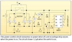
An ideal low-battery cut-off circuit should have zero on-resistance, zero power consumption when the switch is off, and zero power consumption when the switch is on. The circuit shown in the figure meets the first two criteria. In regard to the final requirement, the current consumption of the circuit is only about 1.2 µA.
To reduce the on-resistance to zero, a latching relay (AGN2104H from NASI) is used as the power switch. The coil of the latching relay is directly driven by two CMOS gates connected in parallel to increase the drive capability.
The MAX917 is an ultra-low-power comparator with a built-in 1.245-V voltage reference. The battery voltage, which is divided by R3 and R4, is compared to this reference. When the divided voltage is higher than the reference, the MAX917 output is high. Otherwise the output remains low. In the figure, R3 is 10M and R4 is 4.7M to handle a fourcell NiCd battery pack. The threshold voltage is (R3+R4)/R4 * VREF = (10M + 4.7M)/4.7M * 1.245 V = 3.9 V.
Switches S1 and S2 are for power on and power off, respectively. When S1 is depressed, the battery voltage is applied to IC1 and IC2. If the voltage is higher than 3.9 V, the output of the MAX917 is high. This forces the output of a flip-flop formed by IC1A, IC1F, and R2 to go high. Such a high level immediately forces the right side of the coil to become low. Meanwhile, the left side of the coil remains high while C1 charges up. Thus, the coil of the latching relay will receive a short pulse to turn the switch on. If the battery voltage becomes lower than 3.9 V, the coil will receive another short pulse with reversed polarity that turns the switch off. R1 and C1 determine the on/off pulse width.
The switch can be turned off manually by pressing switch S2. An additional RC filter added between the MAX917’s output and IC1A’s input can increase the circuit’s noise immunity.

