Calculate Hold-Up Capacitor Size For Switching, Linear Regulators
Many power supplies use hold-up capacitors to keep enough energy at the full-wave or bridge rectifier output to supply a load when the rectified voltage drops and rises again at the next half-cycle of the ac supply voltage. When the rectified line voltage goes below the voltage across the hold-up capacitor, the capacitor feeds the power converter circuitry that follows it. As a result, this capacitor ensures smooth, no-dropout operation for the entire power supply.
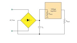
The hold-up capacitor is charged from the rectifier output, through the very low resistance of the rectifier and ac line, so the voltage across the capacitor follows the rectified line voltage as it charges (Fig. 1). The capacitor then discharges through the power converter supplying the load. There is a big difference in the hold-up capacitor’s required value when it supplies a switching regulator compared to a linear one, so we’ll look at them separately.
Switching Regulator Supply
We can neglect power loss in a switching regulator due to its high efficiency.
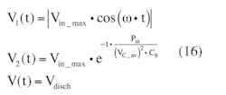
describes the hold-up capacitor voltage while charging. (The absolute-value sign is used to describe the rectifier action.) Vin_max is the peak value of the rectified voltage. The hold-up capacitor voltage, while discharging, is defined by:
where Pin is the converter’s input average power, and VC is the present hold-up capacitor voltage. With these parameters, the equivalent discharge resistance rdisch can be used to determine Ch, the hold-up capacitance. Note that VC is essentially equal to VHoldUp(t) here.
These charge and discharge curves meet up in another cycle, at time t0:
By cancelling out Vin_max, we obtain:
To obtain the value of the average voltage VC_av of the hold-up capacitor, define rdisch using:
Note that the VC changes while Ch discharges, with the same changes as rdisch. To simplify the analysis, we have to find out the average value for the discharge resistance. VC changes exponentially from Vin_max through Vdisch. We know the values of Vin_max and Vdisch, and assuming the discharge process is linear, we can find the voltage across average value of Ch using:
This voltage value can be used to calculate the discharge-process time constant:
The expression of:
represents the hold-up capacitor discharge time constant.
Solving Equation 4 with respect to Ch, we obtain:
This is a transcendental equation with respect to t0 and is very hard to solve symbolically, although it would be very interesting to use it to obtain the value for t0 directly and then figure out how the “meeting point” t0 depends on the capacitance of the hold-up capacitor.
Instead, solve the equation with respect to Ch. When Ch discharges, it does so until it reaches a pre-determined threshold voltage Vdisch for the time interval t0 using:
which results in:
Substituting Equation 7 into Equation 5, we obtain:
from which we get:
This equation shows that to provide the discharge voltage of Vdisch at some load value and line frequency ω the hold-up capacitor should have the value of Ch.
Example 1
With a line voltage Vline = 415 V, load power Pload = 70 W, and efficiency η = 97.2%, then:
Vin_max = √2 × Vline = 587 V
Assign:
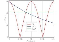
Vdisch = √2/2 × Vin_max = 415 V at f = 50 Hz, ω = 2πf = 314 sec-1, and Pin = Pload/η = 72 W
From this we obtain a value for VC_av:
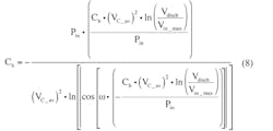
which leads to a value for the hold-up capacitor:
with Ch = 6.21 × 10⁻⁶F, which is a fairly high value for a hold-up capacitor.
We can plot a graph for this example (Fig. 2).
As discharge-margin Vdisch is lowered, more energy should be supplied to the hold-up capacitor to fully charge it, as seen from:
At this point, the hold-up capacitor starts to charge, as indicated by:
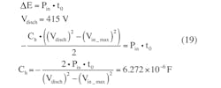
We can calculate the hold-up capacitance value from the point of view of the energy balance:
which shows the amount of energy stored in the hold-up capacitor that should feed the load while the capacitor is discharging, as well as the discharge voltage and the hold capacitor values.
Linear Regulator Supply
The situation for a linear regulator is very different than for a switching regulator. With Vload as the voltage across the load, and Pload as the power to the load, we clearly have:
The linear regulator resistance is given by:
[EQUATION 21]
The time constant is given by:
Substituting this into Equation 4 yields:
and solving with respect to Ch we get:
When Ch discharges, we find Vdisch from:
which leads to t0:
Substitute Equation 26 into Equation 24 to obtain:
and then solve with respect to Ch via:
Example 2
Use Pload = 70 W and Vload = Vdisch – 2.5 V. Then determine Ch via:
If a schematic has a linear regulator, the hold-up capacitor will have higher value because it should store enough energy to supply power loss across the linear regulator.
About the Author
Gregory Mirsky
Princpal Electrical Engineer
Gregory Mirsky is a principal electrical engineer at Atlas Materials Testing Company (an Ametek Company). He holds an MS from the St. Petersburg Baltic Technical University, Russia, and a PhD from the Moscow State Pedagogical University.
