Download this article in .PDF format
Efficiency is the name of the game in power-system design, driven by the need to better leverage available energy and deliver more power from a smaller package. Except in some specialized or extremely low-cost applications, most designs handling high voltage and current use switching technology for motor drives, inverters, and offline power supplies.
The choice of power switching devices has steadily expanded over the years: silicon-based power MOSFETs, IGBTs, and bipolar transistors have now been joined by newer devices based on wide-bandgap (WBG) semiconductors such as silicon carbide (SiC) or gallium nitride (GaN).
Another long-term design trend is the increase in power-transistor switching frequency, since it reduces switching losses and allows the use of smaller magnetic components. The adoption of WBG devices extends these advantages to power levels in the kilowatt range.
Meeting Power-Transistor Drive Requirements
A MOSFET has a significant gate capacitance that must be charged or discharged whenever the device is switched on or off. The drive circuit must supply high peak current to quickly turn on the MOSFET. Conversely, the driver is required to sink a similar amount of current to ground to turn off the device. This sequence repeats at the operating frequency of the power transistor.
Increasing the switching frequency imposes additional requirements on the driver circuitry, including operation at voltages of 5 V or lower, low propagation delay, tight matching between channels, and minimum parasitic inductance.
A complex power design often relies on a digital device such as a microcontroller to control the power delivery, calculate pulse-width-modulation (PWM) frequency, handle diagnostics, and generate the turn-on or turn-off signal. Why can’t it drive the power transistor directly?
A microcontroller does many things very well, but supplying significant current at a high switching frequency is not one of them. A typical output pin is often a 3.3-V logic signal capable of sourcing or sinking only a few milliamps—far less than required to charge the MOSFET gate capacitance in the time available. In addition, many power devices require turn-on voltages greater than 3.3 V.
A high-current gate driver between the controller output and the power-transistor input solves the problem. It combines both the level-shifting and current-drive functions. Furthermore, locating the gate driver physically close to the power switch can help minimize the effects of high-frequency switching noise on sensitive parts of the design.
Although a gate driver can be integrated into a specialized power-controller IC, a separate device allows the controller to run cooler by removing a significant source of heat. Many gate-driver ICs are available with thermally-efficient power packages that include exposed pads for heat dissipation.
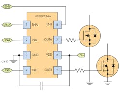
Figure 1 shows the standard direct-drive application. The UCC27524 is a dual gate driver that can sink or source up to 5 A into capacitive loads. The two channels have matched propagation delays, which helps in applications with critical timing requirements, such as synchronous rectifiers. The inputs are compatible with TTL- and CMOS-logic thresholds, and each channel has a dedicated enable pin.
The device features fast rise and fall times of 7 ns and 6 ns, respectively, and a typical propagation delay of 13 ns with 1-ns matching between channels. It’s available in an exposed-pad DGN package.
Other Gate-Driver Applications
Gate drivers are designed to drive power transistors directly, which are capacitive in nature. However, they can also drive them indirectly via a gate-drive transformer, which, of course, is an inductive load. A high-power relay is another inductive load that’s widely used in applications such as automotive electronics and the Smart Grid, and gate drivers are applicable here, too.
Although the current required to energize a coil is less than the hold-in current, a standard relay still requires a continuous application of power to maintain a desired state. A more energy-conscious approach is to use a latching relay that maintains its contact position after removing the control power. A latching relay allows control of the contacts via a single pulse to the relay control circuit; it’s also desirable if the relay must maintain its position during a power loss.
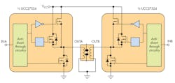
Figure 2 shows a UCC27524 driving a latching relay. In this dual-coil device, a 100-ms pulse is applied to Coil A (OUTA), which turns the relay on; a similar pulse applied to Coil B (OUTB) turns the relay off. Repeated pulses on a coil have no effect.
Relay drives operate at low frequencies, less than 1 Hz, with pulses of 20 to 200 ms in length. The coil resistance limits the gate driver’s peak current.
The Need for Isolated Drivers
The high voltages and currents in many power designs are inherently dangerous: Safety standards like VDE 0884, IEC 60950, and similar requirements from other agencies, require the isolation of potentially lethal voltages and currents from possible human contact.
An isolated switched-mode power-supply (SMPS) topology uses the isolation between the primary and secondary coils of a transformer to accomplish this task for the power path. However, designers must isolate control and feedback signals, too, a requirement that can be satisfied by adding isolation capability to other circuit components.
In addition to its primary function, an isolated amplifier, gate driver, or other device includes a high-voltage isolation component or barrier; a transmitter that modulates the input signal to pass it across the isolation barrier; and a receiver on the other side of the barrier to demodulate the signal back into the original form. Depending on the device, the input and output signals can be either analog or digital in nature. TI offers numerous isolation devices for a variety of applications. A detailed design guide can be found here.
Several levels of isolation are defined in the safety standards:
• Basic isolation can provide protection against high voltage so long as the barrier is intact, but it needs to be combined with another isolation barrier if human access is possible.
• Reinforced isolation is equivalent to two basic isolation barriers in series, and is sufficient by itself as a safety barrier against high voltage.
• Functional isolation is sufficient to enable the system to function properly, but doesn’t necessarily provide protection against shock.
The UC21520 Isolated Gate Driver
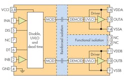
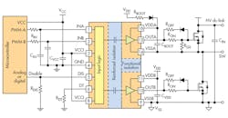
The UCC21520 saves cost and space by combining two functions in a single device (Fig. 3). It’s an isolated dual-channel gate driver that can drive power MOSFETs, IGBTs, and SiC MOSFETs. The device can source up to 4-A peak current and sink up to 6 A, and switches at up to 5MHz.
A 5.7-kVRMS reinforced isolation barrier isolates the input side from the two output drivers; the barrier can withstand a minimum of 100-V/ns common-mode transient immunity (CMTI). Internal functional isolation between the two secondary-side drivers allows for a working voltage of up to 1500 V dc.
The part can be configured as a half-bridge driver with programmable dead time (DT), two low-side drivers, or two high-side drivers. It operates with a VDD supply voltage of up to 25 V. A VCCI range from 3 to 18 V allows the UCC21520 to interface with both analog and digital controllers, and all of the supply voltage pins have undervoltage lockout (UVLO) protection.
The UCC21520 employs capacitive isolation technology; high-voltage silicon-dioxide (SiO2) capacitors act as the isolation components. SiO2 is an excellent dielectric with high dielectric strength. Unlike polyimide and other polymer-based insulators, it’s void-free and its reliability doesn’t degrade with exposure to ambient moisture.
Application Example: Isolated Power Topology
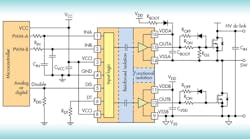
The circuit in Fig. 4 shows the UCC21520 driving a typical half-bridge configuration. The part is applicable to several power-converter topologies such as synchronous buck, synchronous boost, half-bridge, and full bridge. Other applications include three-phase motor drives, solar inverters, and battery chargers for electric vehicles.
Application Example: Three-Phase Inverter
A power inverter is a circuit or device that converts direct current (dc) into alternating current (ac). As its name implies, a three-phase inverter consists of three separate circuits with coordinated outputs to generate a three-phase ac drive. Three-phase inverters have numerous applications in uninterruptible power supplies (UPS), solar inverters, and variable-frequency drives for speed control of ac motors.
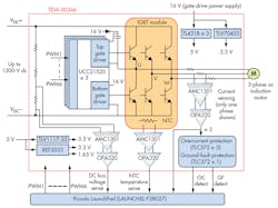
Figure 5 shows the block diagram for a three-phase inverter reference design for an ac induction motor; the design is capable of up to 10 kW. Each phase requires a single UCC21520 that drives both the high-side and low-side IGBTs and an AMC1301 reinforced-isolation amplifier to measure phase current.
The insulated gate bipolar transistor (IGBT) is a voltage-controlled device that combines the high input impedance of a MOSFET with the high current output of a bipolar transistor. IGBTs are popular for medium- to high-power-level designs (a few kilowatts to a few megawatts), especially in PWM applications requiring high dynamic range and low noise.
A TMS320F28027 microcontroller, part of TI’s 32-bit Piccolo family, provides the overall control.
Conclusion
A gate driver is a versatile component that helps solve a number of power-driving problems. TI offers both isolated and non-isolated devices that can drive both capacitive and inductive loads ranging from MOSFETs to WBG devices to relays.
A variety of devices is available with different operating voltages and drive currents. More information on TI’s gate-driver product line can be found here.
