A Guide to Wireless Connectors

Download this article in PDF format.
Wireless-power-transfer (WPT) technology using near-field magnetic coupling (NFMC) has been gaining a lot of attention, primarily in the area of wireless charging for applications like smartphone applications. However, there exists another class of products commonly referred to as “wireless connectors” (WiCo), or “wireless couplers,” that utilize the same physical principles.
Wireless connectors are important for applications where conventional mechanical connectors may not be reliable, or in some cases not even possible to use. Examples of the issues that connectors may face include intrusion from liquid, dirt, and/or corrosive environments. In addition, physical electrical connections become challenging when a situation demands freedom of movement between two or more systems.
Common applications that must deal with these challenges can be found in a wide range of industrial automation environments, where power and/or data must transfer through fluids or walls. Another area well-suited for wireless connectors is in the medical-device field, which demands a high level of reliability, even if exposed to fluids and mechanical bending stresses. Surgical instruments and other such devices fall into this category.
Other applications that could benefit from wireless connectors include robotics, automotive, and some consumer products. It’s fair to say that wireless connectors, and the technology that enables it, will play an ever-increasing role in relieving the “pain points” of conventional mechanical connectors.
This article will provide an overview of wireless-power technology relevant to connectors, the pros and cons of wireless connectors compared to mechanical systems, and considerations when applying wireless connectors. Also included is an example of an ultra-small wireless connector.
WPT as Applied to Connectors
If one looks at the traditional contact-based connector market, it’s easy to conclude that there isn’t a one-size-fits-all for connectors. The sizes and the number of contact pins that form the connector vary widely. Similar to the contact-based connectors, it’s expected that WiCo will also need to be of different types. Therefore, developers and customers (in this case the OEM) must recognize that, like traditional connectors, custom development will be required for most connectors.
Most devices in the market that currently use wireless power for battery-charging applications follow an established standard (such as Qi1 or AirFuel2) to satisfy interoperability and performance requirements. However, these standards are primarily for consumer electronics applications.
While repurposing of the hardware could allow for some wireless-connector applications, limitations will be imposed, for example, on coupling, data rates, BOM, range, etc. Furthermore, for WiCo, interoperability may not necessarily be needed since the system is typically “closed,” meaning there will always be a known transmitter and corresponding receiver (“a mated pair”). This gives the designer options for customization and cost optimization.
That being said, it’s conceivable that some classes of wireless connectors may evolve as standards, similar to USB for wired connectors. For this to happen, the solution(s) will need to address a common problem across an industry or industries.
The design of a WiCo system depends on a several application-driven factors, including:
- Spatial freedom: The maximum allowable distance (air gap) between the transmitter and receiver in all three dimensions (x, y, z).
- Power required at the receiver output: The regulated output voltage and maximum load current that that must be supported.
- Thermal considerations: This is closely related to the end-to-end efficiency (power-in/power-out) of the system. Some applications can’t tolerate excessive temperature rise.
- Size: The physical size of the transmitter and receiver is often a key constraint.
- Environmental requirements: The wireless connector may be exposed to extreme temperatures and/or liquid intrusion.
- Cost: Depending on the application, cost may play a major role in the design approach.
NFMC and Communication
For NFMC applications, antenna (coil) size is wide-ranging, typically greater than about 25 mm in diameter. Preferred frequencies range from 10 kHz to about 13.56 MHz. A high-level discussion on the system aspects and standards defining adoption in the consumer electronics domain can be found in references 1, 2, 3, and 4.
The approximate theoretical maximum range for NFMC is the effective near field at the operating frequency. It’s defined as any distance less than (λ/2π), where λ is the effective wavelength. For example, at 10 kHz, the Rangemaximum ~ 4.7 kilometers, and at 13.56 MHz, the Rangemaximum~ 3.5 meters. The realistic range is much smaller and depends on factors such as the environment, size of the antennas, desired efficiency, power levels, regulatory considerations, etc.
Both magnetic induction (MI) and magnetic resonance (MR) use the same physical principle, i.e., a time-varying current in the transmitter antenna is used to create a time-varying magnetic field that induces a voltage in a receiver antenna. The “generally accepted” distinction between MI and MR lies in the use of reactive components to reduce the reactive impedance looking into the antenna—MI doesn’t use it; MR uses it. In reality, all systems known to the authors use capacitive components to alter the effective impedance looking into the antennas, both on the receiver side and the transmitter side.
Don’t Forget Detection
Any type of wireless power transfer will require some form of detection and control. In its most elementary form, the transmitter detects the presence of a receiver, which starts drawing power as soon as the rectified voltage crosses a threshold value.
The detection mechanism can be as simplistic as a single bit indicating the presence or absence of a receiver via an impedance shift detected as a voltage sense. Or it can be relatively complicated, requiring unique identification (ID) and subsequent power control. The ID bit streams can be read via load modulation of the power carrier (in-band communication), or it may be implemented on a separate communication channel.
When in-band communication is used, modulation schemes such as amplitude-shift keying (ASK), frequency-shift keying (FSK), and phase-shift keying (PSK) are common. ASK is relatively simple to implement but has lower noise immunity, which can be a problem when operating in low-coupling scenarios. Immunity to noise can be increased by utilizing schemes based on FSK and PSK, but they’re more complex.
If a separate communication channel is used, several of the standard wireless-communication technologies can be utilized, such as Transfer Jet, BLE, and NFMI. A separate channel will likely provide more immunity to noise and provide a higher data rate, but will incur development cost and complexity, as well as increase real-estate requirements.
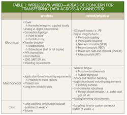
Challenges always must be overcome when moving data from one place to another, regardless of the transmission medium. Common issues that must be managed due to a physical/wired connection are summarized in Table 1.
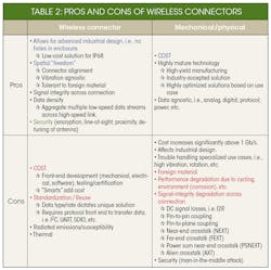
The system designer must consider these various concerns that may apply in the specific application. As with any design decision, pros and cons emerge when comparing wireless connectors versus traditional mechanical connectors (Table 2).
Example Solution
Keeping in mind that a diversity of use cases will require unique implementations, an example miniature wireless-power connector described here could be utilized as a surface-mount device for a pick-and-place type assembly in which existing technology would not be useful. The motivation for this development was the need to replace a pin-based connector operating in a harsh environment that included fluids and mechanical movement.
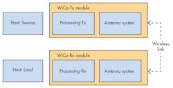
1. Here’s a high-level system diagram of the wireless-connector (WiCo) system.
The dimensions available for this connector were approximately 11 × 5 × 5 mm, and the desired power transfer was about 50 to 200 mW over a distance that varies from 0.5 to 2mm. The key benchmarks for any producible solution are performance, reliable manufacturing, and cost.
The small size made it necessary to operate the system in the high-frequency (HF) regime to obtain sufficient voltage gain to power up the microcontroller (MCU) on the receiver side. Apart from regulatory aspects, the frequency selection also needs to consider the losses in materials in a compact environment, since the eddy currents are higher at HF. The unique impedance changes due to the load requirements, and the range warranted a non-standard rectifier circuit coupled with a shunt-series based off-resonance capacitive tuning.
Standard printed-circuit-board (PCB) and flexible-PCB techniques were utilized for the “muscle” of the system. The muscle comprised the inverter stage, the impedance-matching network, the receiver-sense, and the antenna. The “brain” of the system, i.e. the MCU, was placed on the host board, onto which this WiCo was soldered. For the application under consideration, the MCU was also responsible for other functions of the system.
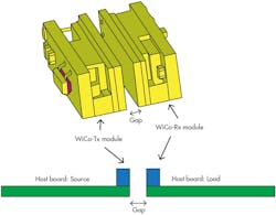
2. Shown is the physical embodiment of the WiCo modules (top) and an example implementation (bottom).
In miniature NFMC-type systems, the magnetics can be one of the dominant problems that defines the frequency of operation and topology. For example, the small size in this example mandated HF operation. Magnetics becomes a complex issue due to increased proximity effects caused by the high frequency of operation, and due to the small size of the antenna. Good design techniques and technology is required to maintain a high antenna-to-antenna efficiency over the entire operating range to prevent thermal shutdowns of the system. Figure 1 provides a generic block diagram of the WiCo system, while Figure 2 illustrates the physical embodiment and exemplary placement on a host board.
Conclusion
Wireless connectors are an excellent choice when transferring power and/or data in harsh environments, while also supporting freedom of movement. As WPT advances continue and costs decrease, we should expect to see wireless connectors used in a wider array of applications.
References:
1. https://www.wirelesspowerconsortium.com/
3. https://www.wirelessdesignmag.com/article/2016/10/wireless-charging-standards-reading-tarot-cards
4. http://www.androidauthority.com/wireless-charging-qi-pad-technology-580015/

About the Author
Robert Giometti
VP of Engineering
Mark D. Melone
System Architect
Dr. Vinit Singh
Chief Technology Officer
Comment About the Article
To join the conversation, and become an exclusive member of Electronic Design, create an account today!

Leaders relevant to this article: