High-Side Load Driver Enhances Short-Circuit Protection

This article is part of the Ideas for Design Series: Vol. 3, No. 8.
This circuit builds on a previous idea in which the addition of an optocoupler to a microcontroller output converted a “dumb” high-side driver into a “smart” one with diagnostics and short-circuit protection.1
The circuit adapts this concept for cases where a microcontroller is either not required or inappropriate. It also adds short-circuit load protection to an even “dumber” driver such as the output of a simple logic gate (Fig. 1). As a result, it too allows a “dumb” low-level device to control a high-power load operating at a much higher voltage without fear of destructive short-circuit conditions.

Assume that C1 is initially uncharged, the driver output is at 0 V, and N-channel MOSFET Q1 is off. When the driver output transitions from a low level to a high level, the pulse couples through C1 and R2 to the gate of Q1, turning it on. Without the feedback provided via optocoupler U1, capacitor C1 would rapidly charge via R1, Q1’s gate voltage would fall to zero, and the MOSFET would turn off after about a millisecond. However, the presence of the optocoupler effectively allows the circuit to monitor the voltage across the load.
If the load is normal, the full supply voltage (+VS) appears across it when Q1 turns on, forward-biasing U1’s photodiode via R3. This turns on U1’s phototransistor, which shunts C1, pulling Q1’s gate up to the high-level drive voltage. Since C1 is now effectively “clamped” by U1’s phototransistor, it cannot charge up, so Q1 remains on and the load remains energized.
If the load is short-circuited at any time by a fault, though, U1’s phototransistor turns off, C1 rapidly charges via R1, and Q1’s gate voltage quickly falls to zero. The MOSFET now turns off, disrupting current flow to the faulty load, and remains off until the driver output is cycled low (to allow C1 to discharge) and then high again. The circuit will continue to “reset” to the off condition until the load fault is removed.
Resistor R2 provides current limiting to prevent Q1’s gate-source capacitance damaging the driver’s output at turn-on. It may also be necessary to prevent the MOSFET from oscillating. A value of a few hundred ohms is usually suitable.
Figure 2 shows the operation of a circuit built with a BUK455-60A MOSFET for Q1. Load-supply voltage +VS was 12 V, the load was 100 Ω, and the driving signal was a 60-Hz, 5-V square wave.
In normal operation (Fig. 2a), a high level at the drive signal results in a low level at Q1’s drain terminal (full supply voltage dropped across the load). In Figure 2b, the load has been short-circuited.
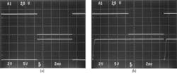
When the driver signal goes high, the circuit output at Q1’s drain terminal falls to zero only for a very brief time (less than a millisecond) and then immediately rises back up to +12 V. In other words, the full supply voltage only appears across the faulty load for less than a millisecond until the circuit “resets,” causing the voltage across the load to drop to zero.
In the case of the faulty load, the C1/R1 time constant largely determines the duration of the brief “on” pulse. If this time constant is too short, the optocoupler will not have time to turn on properly to clamp C1 in the case of a normal load. But if the time constant is too long, a short-circuited load could cause the pulse current rating of Q1 to be exceeded during the brief “on” pulse, potentially damaging the MOSFET.
Using C1 of 22 nF and R1 of 56 kΩ worked well in the test circuit. An optional current-limiting resistor RCL (usually a few ohms) in series with Q1’s drain may be advisable to limit the maximum output current to a safe level.
Reference
1. “Add Short-Circuit Protection, Diagnostics To Automotive High-Side/Low-Side Driver,” Vishwas Vaidya, Electronic Design, March 7, 2013.
Anthony H. Smith has been working as a consultant engineer for the past decade, designing products for the industrial, domestic, and automotive markets. He received a BSc (Honors) in electronics from Salford University, Greater Manchester. He also holds two patents. He can be reached at [email protected].
About the Author
Anthony Smith
Consultant Engineer
Anthony M. Smith has been working as a consultant engineer for the past decade, designing products for the industrial, domestic, and automotive markets. He received a BSc (Honors) in electronics from Salford University, Greater Manchester. He also holds two patents.
Comment About the Article
To join the conversation, and become an exclusive member of Electronic Design, create an account today!

Leaders relevant to this article: