How to Wirelessly Power and Access a 1-Wire Network (Part 1)

1-Wire devices only use a single conductor and ground to provide functionality in mechanical assemblies and electronic systems. As a result, communication and power delivery on a 1-Wire bus reduce the number of nodes required in a system to just one.
By adding symmetric/asymmetric authentication, identification, memory, data acquisition, and control, 1-Wire technology equips users with secure asset and information management. 1-Wire technology also provides hardware-based security in a low-power design that’s essential for every application: cloud networks, consumable pharmaceuticals and healthcare equipment, mobile sales channels, automotive, and the smart grid.
A near-field communications (NFC) transceiver—with a built-in 256-bit secure hash algorithm (SHA-256) co-processor for symmetric authentication—paired with an NFC transponder that includes an I2C master/slave port and an energy-harvesting output, provides security for wireless access to a node of closed portable devices. NFC systems compatible with ISO-15693 and FIPS 180-4 provide a wireless method to power and securely access 1-Wire devices. Wireless access to a 1-Wire network provides new use cases and additional flexibility for electronics in applications where NFC is the preferred method of wireless power transfer and communication.
Wireless to 1-Wire Bridge
Wireless access to a 1-Wire network involves translation between a wireless communication protocol such as NFC and the 1-Wire communication protocol. Most major smartphone brands already incorporate NFC so that users can connect to electronics and unpowered objects such as key fobs, labels, and cards. Thus, an NFC-equipped smartphone/device can wirelessly access a 1-Wire network.
In an NFC system, the transceiver is the initiator and produces an RF field to provide power, send function commands, and permit information exchange. The transponder powers itself from the RF field generated by the transceiver. It also receives function commands to execute and relays data from memory or from attached devices to the NFC reader.
NFC relies on electromagnetic induction between nearby antennas to transmit and receive power, obtain control, and transfer data. By utilizing properly routed PCB traces or wound wire in a calculated manner, a transceiver can initiate communication with a transponder.
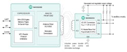
1. An NFC system consisting of the MAX66300 transceiver and the MAX66242 transponder. Ancillary circuitry is connected to the MAX66242 VOUT, I2C interface, and the PIO.
Figure 1 illustrates an NFC hardware setup using a transceiver such as the MAX66300 and a transponder like the MAX66242, both developed by Maxim Integrated. There are two functional features provided by the MAX66242 transponder that enables wireless access to attached ancillary circuitry:
- An internal ac-dc converter allows power conversion from the harvested RF field to a regulated output voltage at VOUT. As a result, the MAX66242 can power attached ancillary circuitry, the I2C interface, and the programmable input-output (PIO).
- An integrated I2C master and slave interface allows for bidirectional access and control.
While in the I2C master mode, the MAX66242 can relay information from connected circuitry such as sensors, a microcontroller, and other ancillary circuitry to an NFC transceiver such as the MAX66300 or a smartphone. In the I2C slave mode, the MAX66242 can serve as an intermediary between connected host circuitry and an NFC transceiver.
The PIO provides additional functional features: It can enable ancillary circuitry when the NFC link is ready for communication; provide general-purpose control; and provide monitoring information. For detailed information on the PIO, refer to the MAX66242 unabridged datasheet.
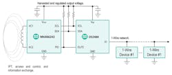
2. Wireless to 1-Wire bridge—the MAX66242 powers the DS2484 and 1-Wire devices via VOUT.
To access and control a 1-Wire network, the MAX66242 requires bidirectional I2C and 1-Wire protocol translation. An I2C-to-1-Wire bridge such as the DS2484 facilitates this task. Figure 2 shows how I2C and 1-Wire protocol translation is accomplished using the MAX66242 and DS2484.
The DS2484 complements the MAX66242 by converting between I2C and 1-Wire protocol with adjustable timing and a sleep mode. By allowing the MAX66242 to place the DS2484 in sleep mode via , the DS2484 can power up when required by the NFC transceiver. The 1-Wire network can start to power up for communication only after the power-down (PDN) bit is toggled to zero in the DS2484 configuration register.
If the application requires symmetric key-based authentication of the 1-Wire network, the MAX66242 provides a built-in SHA-256 engine for computing a message authentication code (MAC) under FIPS 180-4. If asymmetric public-key based authentication is required, the DS2475, which is an elliptic-curve digital signature algorithm (ECDSA) co-processor with I2C to 1-Wire master capability, can be used in place of the DS2484. The DS2475 generates certificates and signatures under the P-256 curve. For more information on the P-256 curve, check out the National Institute of Standards and Technology’s (NIST) site.
Powering a 1-Wire Network Using Harvested VOUT and IOUT
The MAX66300 and the MAX66242 complete an NFC system that meets the ISO 15693 and the FIPS 180-4. If both are connected to individual printed-circuit-board (PCB) antennas tuned to 13.56 MHz, characterization of the MAX66242 harvested output voltage VOUT and output current IOUT is possible. The measured results in this section were obtained using the MAX66300-X24EVKIT, which includes the MAX66300 and MAX66242.
Figure 3 shows the available voltage at VOUT harvested by the MAX66242 concerning the distance from the MAX66300 antenna. The voltage values for VOUT shown are obtained when both the transmit and receive antennas are parallel and centered to each other.
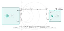
3. MAX66242 VOUT versus distance from MAX66300’s loop antenna.
The MAX66300 output driver antenna configuration in Fig. 3 uses on-off keying (OOK) and drives the antenna differentially using the ANT1 and ANT2 pins. The voltage at VOUT varies with different antenna configurations, orientations, and environments (e.g., in the presence of nearby metals, other transponders in the read zone, etc.) At 3.2 cm or less, VOUT can output 3.3V or 1.8 V depending on user configuration. At distances greater than 10.2 cm, no harvested voltage regulation is present at VOUT.
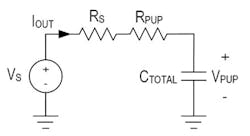
To wirelessly power, access, and control a 1-Wire network, the energy harvested from the NFC link must power the MAX66242, the DS2484, and the 1-Wire devices as shown in Fig. 2. Understanding the amount of IOUT current available from the harvested output voltage VOUT is critical for the design of an NFC-powered 1-Wire network. Figure 4 models IOUT and VOUT as an ideal rectified voltage VS and source resistance RS.
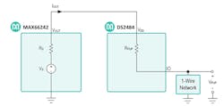
4. VOUT is modeled as an ideal voltage supply VS and source resistance RS. VDD is the voltage supply for the DS2484. The 1-Wire network pull-up voltage is VPUP. RPUP is the pull-up resistance of the 1-Wire network.
The ideal rectified voltage VS is equal to the open-circuit voltage at VOUT. The source resistance RS effectively increases the pull-up resistance of the 1-Wire network to RS + RPUP, where RPUP is internal to the DS2484. For more information on the resistance value of RPUP, including the active pull-up (APU) and the strong pull-up (SPU), refer to the DS2484 datasheet. VDD is the voltage supply for the DS2484. Note that VOUT shares the same node as VDD and, therefore, are equal. The 1-Wire network pull-up voltage is VPUP. Figure 5 shows the load regulation of VOUT with the same configuration described in Fig. 3 at a distance of 0 cm from the NFC transceiver’s antenna.
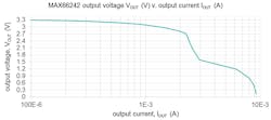
5. Output voltage VOUT versus output current IOUT for 3.3-V VOUT mode.
The output voltage VOUT is defined as the ideal rectified voltage VS minus the voltage drop across the source resistance RS due to IOUT. Therefore, the source resistance RS is defined in the following way in Equation 1:
RS = (VS – VOUT)/IOUT (1)
Figure 6 shows how the source resistance RS varies concerning the measured output current IOUT when the output voltage VOUT is set to the 3.3-V mode. RS exhibits nonlinear characteristics due to difficulty in maintaining a constant harvested VOUT with an increasing IOUT demand.
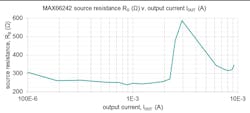
6. Source resistance RS for 3.3-V VOUT mode.
Not only does RS depend on IOUT and VOUT, but it’s also initially influenced by the internal pull-up resistance RPUP of the DS2484. This means that if the 1-Wire network in Fig. 4 were to be represented by an equivalent discharged capacitance CTOTAL as shown in Figure 7, RS would have a value dependent on VOUT and on an IOUT that’s initially set by RPUP.
7. Simplified RC circuit that models the branch connection of the MAX66242 and DS2484 in Fig. 4.
As CTOTAL accumulates charge, RS changes over time because IOUT and VOUT also adjust over time. By using Fig. 5, VOUT can be determined by knowing the instantaneous value of IOUT. RS reaches a final value once the charge on CTOT reaches a steady-state value.
Calculating the first RS value requires an iterative approach due to the nonlinearity between IOUT and VOUT. By solving for IOUT and looking up the value of VOUT on Fig. 5, a convergent result for RS can be determined. Figure 8 illustrates the iterative procedure to calculate the initial value for RS for an output current IOUT. Here, a result for RS is considered convergent if IN+1OUT differs by 10% or less compared to INOUT. N represents the number of iterations in the flow diagram.
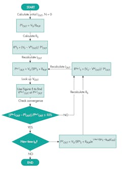
8. Flow diagram to calculate the initial source resistance RS for an output current IOUT. Here, a result for RS is considered close to convergence when two sequentially calculated output currents IOUT differ by 10% or less. The flow diagram also allows you to calculate the RS for a future time tN+k other than the initial time t0.
Note that instead of calculating iterative versions of RS, one can use Fig. 6 in conjunction with Fig. 5 to find a final value. However, it’s recommended to calculate RS using the flow diagram and to use Fig. 5 to look up VOUT as shown in Fig. 8. This way, only one plot instead of two are used for extrapolation from measured results to reduce error.
Fig. 8 can also be used to recalculate the source resistance RS as the equivalent capacitance CTOT continues to accumulate charge at time tN. To do this, set the Boolean for “New time tN?” to ‘YES’ to use the exponential decay function to calculate IOUT at a later time tN+1.
For applications that require more output current IOUT, an NFC transceiver with a high-voltage output driver and high-gain receiver can increase the range and power delivery.
By modeling the regulated voltage harvested from the NFC RF field using the MAX66242 as an RC circuit, the designer can calculate the source resistance added to the 1-Wire pull-up resistance that exists on the 1-Wire network. Calculating the source resistance RS recursively makes it possible to find the output current IOUT supplied by the harvested regulated voltage VOUT of the MAX66242.
Part 2 will discuss how the calculated source resistance RS allows the designer to analyze whether 1-Wire communication is feasible with the harvested RF energy for the NFC link.

About the Author
Norberto Sánchez-Dichi
Associate Member of the Technical Staff
Mohamed Ismael
Senior Member of the Technical Staff, Applications
Comment About the Article
To join the conversation, and become an exclusive member of Electronic Design, create an account today!

Leaders relevant to this article: