Motor-Driver PCB Layout Guidelines (Part 2) (.PDF Download)
Part 1 of this article provided some general recommendations for designing printed-circuit boards (PCBs) using motor-driver ICs, which require careful PCB layout for proper performance. Part 2 discusses some specific PCB layout recommendations for using typical motor-driver IC packages.
Layout for Leaded Packages
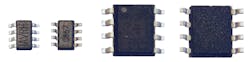
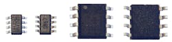
6. SOT-23 and SOIC packages are typically used in low-power motor drivers.
Standard leaded packages, like SOIC and SOT-23 packages, are often used for low-power motor drivers (Fig. 6).
To maximize the power-dissipation capability of leaded packages, Monolithic Power Systems (MPS) uses a “flip-chip on leadframe” construction (Fig. 7). The die is bonded to the metal leads using copper bumps and solder without the use of bond wires. This allows heat to be conducted from the die through the leads to the PCB.
