Power over Ethernet (PoE) now powers more than 100 million end devices, deployed in high-volume applications such as wireless access points (APs) and Internet protocol (IP) phones. Yet the relatively modest amount of power that it can deliver to the device being powered, nominally 25.5 W, has limited its penetration into other applications.
Related Articles
- Integrated PoE-PD Controllers Meet Upcoming PoE+ Standard
- Ethernet Switch Manages Power Over Ethernet Resources
- Automotive Ethernet Arrives
All that is destined to change with the introduction of a new PoE standard, IEEE 802.3bt, which will at least double and perhaps as much as triple the power delivered to the end device. The proposed standard, which has recently entered the Task Force phase, will also explore ways for other devices to provide PoE power beyond the mode(s) presently available by allowing power over all four pairs in the standard Ethernet cable. The IEEE 802.3bt Power over Ethernet Task Force is also looking to standardize PoE with 10GBASE-T (10-Gbit Ethernet).
The ability to deliver higher power to end devices will expand PoE’s application base enormously. Its primary advantage for design engineers has always been anchored in simple economics. Delivering power and data on the same link saves installation costs compared to running separate lines. This makes the installation and relocation of devices as simple as moving a standard CAT5/6 cable, instead of requiring an electrician to move ac sources.
This file type includes high resolution graphics and schematics when applicapable.
System and silicon vendors are already rolling out non-standard products that deliver 60 W or more, at least doubling the power delivered under the existing IEEE 802.3at-2009 standard. This means that before the 802.3bt standard is officially in place, PoE will power high-volume applications such as building management, point-of-sale, and industrial control systems, although in non-standard implementations they must be designed and operated as standalone systems (Table 1).
PoE Basics
The technology refinement that enables increasing power to the end device is at first glance fairly straightforward: increase the number of wires carrying the power. Although a standard CAT5/6 RJ-45 Ethernet cable consists of four pairs of wires, the present PoE standard enables power transmission over just two pairs of the wire. The proposed change to the 802.3 standard uses all four pairs.
This is the third iteration of the PoE standard. The Task Force that was formed to review recommendations for the new standard will consider raising the power to the safety limit of 100 W, or within a reasonable margin. Since issues such as energy dissipation and link length must be considered in every iteration of the standard, a brief history of PoE’s evolution is worth revisiting.
The original IEEE 802.3af standard (2004) defines two basic types of devices: endspans and midspans. Endspans are essentially Ethernet switches with PoE circuits added. They are typically deployed in one of two scenarios: in new installations or in those occasions when the switch will be replaced anyway due to upgrading to a higher-speed Ethernet. Midspans are not integrated into the switch but are positioned between it and the powered device (PD). They are most often deployed when the network owner adds IP phones or wireless APs to an existing non-PoE network. The distinction is worth noting because some functionality available for endspans is not available for midspans.
The standard also specifies how to provide up to 15.4 W of 48-V nominal dc power to each device being powered. Dissipation in the cabling limited power to only 12.95 W being delivered to the PD. Power delivered to the PD is the main driving factor in the subsequent iterations.
IEEE 802.3at (also known as PoE+, 2009) provides up to 30 W of 50-V nominal dc power at the power source element (PSE). Subtracting cable loss yields 25.5 W at the PD. In either standard, the PD must operate with either the two spare pairs (wires 4-5 and 7-8, known as Alt-B) or the two data pairs (1-2 and 3-6, known as Alt-A). IEEE 802.3at defines two types of systems. Type 1 has a maximum power available at the PD of 12.95 W. Type 2 has a maximum power at the PD of 25.5 W. Other parameters such as voltage range also differ between the two types.
Since not all Ethernet-connected devices support PoE, a PD must identify itself as PoE standards-compliant. The designer does this by adding a 25-kΩ resistor between the powered pairs. If the PSE detects a resistance that is too high or too low (including a short circuit), no power is applied. This protects devices that do not support PoE. As previously noted, the current standard supports both 12.95-W and 25.5-W operation at the PD. The detection process is the same for IEEE 802.3af and IEEE 802.3at. Several steps that complete the power-up process follow it (see “PoE Classification And Powering Options”).
IEEE 802.3af is specified to work with 10BASE-T and 100BASE-TX, both of which use two twisted pairs for data transmission. IEEE 802.3at added 1000BASE-T, which uses all four pairs for data transmission. 10GBASE-T PoE links are not specified in the 2004 standard nor the 2009 revision, but this support is necessary to keep pace with the natural market shift toward higher data rates as they become available.
The Dell’Oro Group, a market research firm specializing in networking and telecommunications, has forecast that there will be approximately 9 million Gigabit Wi-Fi nodes deployed by 2017. Recognizing this trend, the study group is working on technology solutions for extending PoE over 10GBASE-T links. The PoE specification can be found in Clause 33 of the recently published IEEE 802.3-2012.
Four Pairs Instead Of Two
While the need to provide more power to the end device is driving the proposed standard, IEEE 802.3bt also will enable more efficient operation. Efficiency is always a design issue in today’s world of energy efficiency awareness. One of the downsides of the transition from 13 W per port to 25.5 W per port is that cable losses increased exponentially. As it turns out, the most effective means of improving efficiency is to inject power into all four pairs because this solution reaps the benefits of the basic squared relationship between current and power.
For the present two-pair PoE solution, cable loss power (PCL) can be calculated as:
PCL = I2 ✕ R
where R is channel resistance and I is the current carried by the two pairs. For a four-pair solution, the equation becomes:
PCL = (I/2)2 ✕ R + (I/2)2 ✕ R
PCL = 2 ✕ (I/2)2 ✕ R
PCL = (1/2) ✕ I2 ✕ R
Assuming that the current remains the same, the four-pair solution experiences one-half the cable loss.
Assuming that the load remains the same, upgrading existing installations to four-pair power is slightly more than 50% more efficient than a two-pair powering system since the current delivery impedance halves. This lowers the total delivered current for a four-pair system to less than half of a two-pair system due to the squared relation of current to power.
Therefore, the total power into the cable + PD system is less because the overall current is less. The actual power saved depends on cable characteristics, but one example would be a 24-port IEEE 802.3at-2009 Type 2 system that delivers 25.5 W per port over a cable run of 100 meters. Upgrading the two-wire solution to a four-wire solution can save more than 60 W in this case.
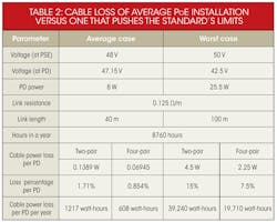
Table 2 compares an average case with a worst-case scenario in terms of power saved. The average PoE installation does not require the maximum power available and has a cable run of about 40 meters. The worst-case scenario uses the maximum 25.5 W and the maximum recommended 100-meter cable run.
Using the conservative estimate of 100 million deployed nodes and the data from Table 2, average cable loss per year worldwide with a two-wire PoE solution is 121.7 million kWh. With the four-wire PoE solution, the cable loss is 60.8 million kWh. In addition to reducing the environmental impact of PoE, a four-wire solution offers operators of large Ethernet-based installations with PoE systems considerable utility cost savings.
It should be noted, however, that losses due to power conversion will always make PoE less efficient than plugging the PD into power mains. As power conversion technology becomes more efficient, the difference will decrease, however, and this also has to be weighed against PoE’s considerable installation cost savings.
As previously mentioned, the four-wire solution has been implemented in a few proprietary solutions. As such, it is mature enough to be recognized as workable and as a potential enhancement to the family of PoE standards.
Power Considerations
With the four-pair solution providing as much as three times as much power at the PSE, the next question is how to handle power budgeting so multiple PDs have the power they need—and so the PSE power supply can be sized correctly. The current PoE standard supports a concept known as power forwarding by which power can be passed through from one device to additional devices.
One frequently cited example is a hotel room where, in addition to powering an AP, PoE is used to power an LED lamp, clock, radio, and other devices in the same equipment cluster. When the IT infrastructure has a backup power supply, this can be particularly useful and convenient for hotel guests.
Another use case for power forwarding enables the placement of switches outside wiring closets. This allows more flexibility in deploying PDs such as APs, IP cameras, point-of-sale devices, printers, secure access control, and building automation devices that do not have access to power outlets.
Some form of power budgeting is necessary for these kinds of power-forwarding applications to be successful. As previously noted, the current standard allows a PD to “negotiate” its power mode in 100-mW steps using the Link Layer Discovery Protocol (LLDP). The standard also specifies five power levels, one default and four optional, that can be handled in hardware. Class 0 (the default) ranges between 0.44 and 12.95 W; Class 1 (very low power), 0.44 to 3.84 W; Class 2 (low power), 3.84 to 6.49 W; Class 3 (mid-power), 6.49 to 12.95 W; and Class 4 (high power), 12.95 to 25.50 W. Only IEEE 802.3at (Type 2) devices can use Class 4.
With the new standard providing considerably more power, PoE can be called upon to power more devices, which will make for a generally more complex scenario. The negotiation process becomes worthy of further consideration, and the IEEE Task Force is working on ways to simplify power budgeting negotiations.
Under the present standard, midspans can implement just the hardware-based negotiation described earlier because they are single-port devices that only insert power and do not interact with the data stream. But since midspans are, by definition, placed in between switches and inject power at that point, they offer an interesting possibility when a system design calls for a long cable run.
If midspans were capable of LLDP communication, it would be possible to run up to 200 m of cable: 100 m from the switch to the midspan and 100 m from the midspan to the PD. Technically, of course, this is no longer a midspan. It becomes a two-port endspan because it has two active Ethernet ports.
Design Considerations
Standards provide a set of best practices and specifications to ensure that products designed to comply with the standard will interoperate with other standard-compliant products. This leaves a large number of design decisions to the designer and, therefore, a number of problems to be avoided.
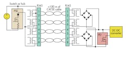
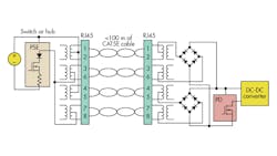
An end-to-end PoE system such as the one shown in the figure involves PSEs, PDs, the switch, cabling, and, importantly, a dc-dc power supply. In other cases, a design may simply be a PD that an installer will integrate into the PoE system. Designers should be aware of certain pitfalls that can affect these designs. They also should keep three tips in mind when designing PDs for PoE systems:
• Designing inrush current protection on the PD is important because the installer may use low-end PoE injectors that don’t have soft-start capability when applying power to a client.
• Use an isolated power supply. Since there are no physical boundaries between the PoE voltage source and the user, voltage spikes or short circuits can create a harmful situation. Designs should include 1500-V ac or 2250-V dc isolation to ensure safety certification.
• Carefully select a package and pin-out for your PD front end plus dc-dc controller that meet the creepage and clearance requirements of UL and other certification organizations. It can prove difficult to find an appropriate pinout in leadless packages. An older package may be a better choice even though it is slightly larger.
Conclusion
PoE is already a compelling option for supplying modest amounts of power to devices that are integrated into an Ethernet network because it significantly reduces installation costs for powering the end device. As such, PoE has already achieved significant market success. Some applications have been locked out of using PoE, however, due to the lower power delivery of the two previous standards.
Extending the power limit and making tweaks to accommodate some new types of PDs can lead to growth. The IEEE is working to meet these challenges by exploring a four-wire solution to increase efficiency to legacy and low-power PDs or to deliver more power to the new applications that could use PoE. The IEEE is also considering proposals that will extend PoE’s utilization to 10GBASE-T links and enhance its ability to adjust power delivered to the power actually required.
Chad Jones is the acting chair of the P802.3bt Task Force and a member of the IEEE 802.3 4-pair Power over Ethernet Study Group. A hardware engineer with a large systems vendor, he currently holds six patents, most related to PoE. He can be reached at [email protected].
This file type includes high resolution graphics and schematics when applicapable.
About the Author
Chad Jones
Acting Chair
Chad Jones is the acting chair of the P802.3bt Task Force and a member of the IEEE 802.3 4-pair Power over Ethernet Study Group. A hardware engineer with a large systems vendor, he currently holds six patents, most related to PoE. He can be reached at [email protected].


