Prevent System Damage Via Fast, Accurate Over-Current Detection
Current measurement can serve as a means for managing system thermal performance.1 One of the main reasons for managing system thermals via current measurement is to prevent system damage via fault detection. Many applications require either indication of an out-of-range current condition or control of system performance in the event of an over-current condition.
These conditions can vary from ground faults or short-circuit events to loading conditions beyond those the system was designed to support. Regardless of the source, protection circuitry needs to be added to ensure that these potentially damaging conditions are not allowed to persist.
This file type includes high resolution graphics and schematics when applicable.
Fuses
Using a fuse is the most common implementation for protecting a system from these conditions. The fuse’s sole purpose is to open in the event of an extended over-current condition. While this approach to protection is very simple and effective in protecting the system from gross, over-current events, there are drawbacks to such an implementation and tradeoffs to consider.
A fuse protection scheme offers protection for a single event, since the fuse is destroyed by the over-current event while protecting the remainder of the system. For the system to become functional again, the fuse must be replaced. This could involve rework at the board level to remove and replace the blown fuse with a new one.
Another potential drawback is that it requires the current to significantly exceed (four times or more) the rating of the fuse for a quick open to occur. This makes it extremely difficult to predict the precise over-current level at which the fuse will open.
The sole use of a fuse as a protection component does not provide information on the system’s actual operating conditions. This is where other options for system protection offer significant performance advantages.
Simple Op Amp Plus Comparator
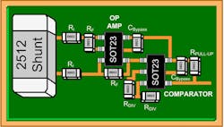
An over-current detection solution can be easily created using a simple, low-cost operational amplifier (op amp), external gain setting resistors, and a low-cost comparator (Fig. 1). A difference amplifier configuration is created using the op amp and external gain setting resistors. A shunt resistor is placed across the input terminals of the difference amplifier.
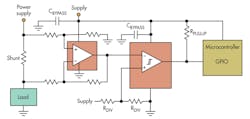
Known as a high-side configuration, the shunt is placed between the supply rail and the load to enable system ground faults. This configuration creates a single-ended output voltage that is directly proportional to the current flowing through the load that is routed to the comparator.
The threshold level of the comparator reference is determined by calculating the appropriate voltage that is applied to the input to the comparator after the gain of the amplifier stage is applied to the voltage drop across the shunt that corresponds to the maximum allowable current:
Vthreshold = Rshunt x Imax x Gain
There are several options for the circuitry used to create the comparator’s threshold reference signal depending on the accuracy and stability required by the application. This reference signal can vary from a simple resistor divider network (lowest cost and least accurate) (Fig. 1, again) to a precision low-drift voltage reference (most expensive and accurate).
The output of the comparator normally is routed to a general-purpose I/O (GPIO) pin on a microcontroller (MCU). The MCU will have code running that will use the signal as an interrupt to implement the system protection algorithms. These could range from simply turning on a cooling system such as a fan to full system shutdown.
Alternatively, the output could be routed to a relay that acts like a fuse and opens up the supply line, preventing system damage. Unlike a fuse, the relay resets once the system is reset, and the current drops below the threshold level.
Current-Sense Amplifier And Comparator
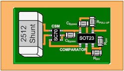
Replacing the op amp with a dedicated current-sense amplifier (also called a current-shunt monitor) in the above scheme can allow for further optimization of system protection (Fig. 2). A current-sense amplifier is a specialized device that integrates the op amp and the gain-setting resistors. This integration of all the discrete components in the measurement portion enables a more accurate measurement while offering a smaller footprint.
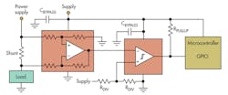
As with the op-amp scheme, the system is configured for high-side detection with the load current creating a voltage drop across the shunt resistor that is amplified by the current-shunt monitor and then routed to the comparator. The output and system protection implementation ultimately would be implemented the same as described above.
Dedicated Over-Current Detector
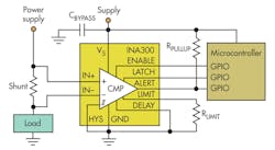
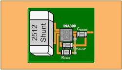
A third option is to integrate all of the detection circuitry into a single device, such as the Texas Instruments INA300. This dedicated current-sensing comparator is optimized for detecting over-current conditions. It integrates the precision measurement circuitry and the comparison portion, creating an all-in-one over-current detection solution (Fig. 3).
The principle of operation is simplified versus that of either of the two-stage implementations described above. The threshold voltage is directly equal to the voltage drop across the shunt resistor corresponding to the maximum current allowed:
Vthreshold = Rshunt x Imax
This adjustable threshold is set using a single external limit-setting resistor or via a voltage input from a digital-to-analog converter (DAC). The output can be configured to operate in either a transparent mode where the output status follows the input state or in a latched mode where the alert output is cleared when the latch is cleared, indicating that the over-current alert has been received. The output is treated just like the output of the comparator described above.
Footprint Revisited
The current-sense amplifier and comparator implementation offers footprint savings over the simple op-amp and comparator implementation. The size of the implementation will vary depending on the actual components chosen, but let’s put some average numbers on the comparison.
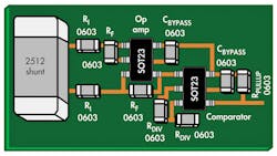
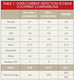
Many typical op amps and comparators utilize the SOT23 package with a 2.8- by 2.9-mm footprint. The first implementation requires two such packages, the shunt resistor (let’s assume it is the same 2512 size for all implementations: 7.25 by 3.85 mm), and eight discrete resistors (Fig. 4). If we use the 0603 size (2.35 by 1.45 mm) for all non-shunt resistors, this leads to a total component footprint (not counting the routing) of just under 75 mm2.
Many current-sense amplifiers utilize a SC-70 package with a footprint of 2.1 by 2.0 mm. This scheme requires five discrete resistors. The footprint for this implementation totals just over 57 mm2, or roughly a 23% savings over the op-amp and comparator scheme (Fig. 5).
One of the most significant advantages of the integrated over-current detector is the integration offered. For example, the INA300 utilizes a 2- by 2-mm package and only requires three external resistors along with the shunt (Fig. 6).
This totals a solution footprint of just over 42 mm2, or a savings versus the alternatives of 44% and 36% respectively (Table 1).
Summary
Over-current detection is key to preventing damage in electronic systems. While a fuse is a very simple and low-cost method for detecting and responding to such conditions, its use as a protection component does not provide information on the actual operating conditions of the system.
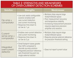
This is where other options for system protection via over-current detection can be employed. Many over-current detection solutions can be optimized based on the key concerns of a particular application, whether that be cost, solution size, measurement accuracy, or alert response time (Table 2).
References
“Use Current Measurement As A Leading Indicator For System Thermal Management,” Dan Harmon, http://electronicdesign.com/power/use-current-measurement-leading-indicator-system-thermal-management
Download a datasheet for the INA300.
Dan Harmon is sensing business development manager for Texas Instruments’ sensing group. In his more than 27 years at TI, he has supported a wide variety of technologies and products including interface products, imaging analog front ends (AFEs), and charge-coupled device (CCD) sensors. He also has served as TI’s USB-IF Representative and TI’s USB 3.0 Promoter’s Group Chair. He earned a BSEE from the University of Dayton and a MSEE from the University of Texas in Arlington. He can be reached at [email protected].
About the Author
Dan Harmon
Marketing Manager, Current and Power Measurement Product Line
Dan Harmon is the marketing manager for the Current and Power Measurement Product Line at Texas Instruments. In his 30-year career at TI, he has supported a wide variety of technologies and products including interface products, imaging analog front-ends (AFEs), and charge-coupled device (CCD) sensors. He also has served as TI’s USB-IF representative and TI’s USB 3.0 Promoter’s Group Chairman. Dan earned a BSEE from the University of Dayton and a MSEE from the University of Texas in Arlington. He can be reached at [email protected].
Comment About the Article
To join the conversation, and become an exclusive member of Electronic Design, create an account today!

Leaders relevant to this article: