Raising the Protection Bar for USB Type-C and USB PD

Download this article in PDF format.
The phrase “raise the bar” has its origin in high jumping and pole vaulting, and is now a metaphorical cliché in many fields. In sports, of course, it has both a metaphorical and a literal meaning. Dick Fosbury raised the high-jump bar metaphorically—his Fosbury Flop technique revolutionized the sport—but not literally, since he never held the world record. That was left to others: Every world record holder since 1978 has been a “flopper,” including Javier Sotomayor (Fig. 1).

Supplying power over a USB connector used to be a relatively sleepy backwater. The arrival of the USB Type-C connector and the associated USB Power Delivery (USB PD) specification changed all that. Unlike USB 2.0’s 2.5 W or the 5 W of USB 3.0 (both 5-V-only systems), USB PD has raised the bar dramatically, ramping up the power-delivery capability of USB to 100 W, delivered as 20 V at 5 A. It has also increased the demands on power-system protection circuitry.
USB Type-C Protection Strategy
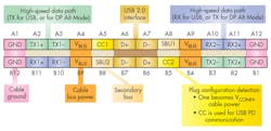
Figure 2 shows the USB Type-C connector pinout. It’s symmetrical; the cable can be inserted “up” or “down” equally, putting an end to the old USB joke, “No matter which way you insert a USB connector, you have an 80% chance of being wrong.”
The Type-C pinout has five sections with different functions:
• Four VBUS/GND power & ground pairs.
• Four differential RX/TX pairs for the USB 3.1 SuperSpeed (10GB/s) mode, if implemented. SuperSpeed requires full-duplex communication.
• Two USB 2.0 D+/D- pairs for USB 2.0 functionality (only one pair used)
• Two Sideband Use (SBU) pins used for USB Alternate Mode (AM) operation to carry non-USB channels such as HDMI or DisplayPort.
• Two Configuration Channel (CC) pins used to detect cable orientation and implement the USB PD Specification.
The pins are subject to different risks based on their functions and their locations in the connector. When discussing protection, we can divide the pins into three classes:
1. The VBUS pins require overvoltage (OV), overcurrent (OC), and reverse-current protection.
2. The four SBU and CC pins adjacent to VBUS require a different type of OV protection, plus protection against electrostatic-discharge (ESD) strikes.
3, The TX/RX pins require only ESD protection.
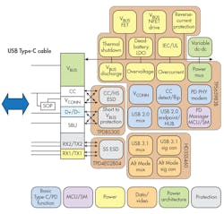
Figure 3 shows the block diagram of a typical USB Type-C port that includes USB PD. The interface is the same at both ends of the cable, so only one end is shown.
Let’s take a closer look at the different protection measures.
Protection for the VBUS Pin
The VBUS protection functions are the responsibility of the TPS65983B standalone USB Type-C and PD controller.
This device performs multiple tasks. In a typical USB PD sequence, the TPS65983B first detects the insertion of a USB Type-C cable into the Type-C socket and determines the cable plug orientation. Upon cable detection, the TPS65983B communicates on the Configuration Channel (CC) wire using the USB PD protocol to negotiate power-delivery features such as source/sink operation and the power level to be used. When negotiations are complete, the TPS65983B enables the appropriate power path and configures AM settings for internal and external multiplexers.
For VBUS, the TPS65983B provides overcurrent, overvoltage (OV), and thermal protection. These are traditional power-device functions, but the VBUS pin on a USB PD port must be able to source and sink current, as well as switch between them as needed.
The USB PD 3.0 Fast Role Swap (FRS) feature raises the bar a notch: It requires the port to switch from sink to source quickly enough to avoid any interruption of power to other devices in a USB PD ecosystem. This situation might occur, for example, if the port is receiving power from a USB PD hub that’s also supplying other devices, and the hub unexpectedly loses power. In such a scenario, the FRS specification requires that the TPS65983B detect the change and switch to operating as a source in under 150 μs so as not to interrupt the VBUS supply. You can find out more about FRS here.
This increased functionality complicates the design of the VBUS supply and protection circuitry. To supply power and overcurrent protection for the various USB PD use cases, the TPS65983B interfaces to the VBUS connector pin via three power paths (Fig. 4). This is a simplified diagram and doesn’t show all possible configuration options. Consult the datasheet for more information. The TPS65983B also provides power to the CC pins, but this isn’t shown.
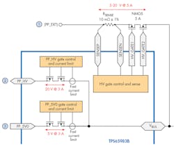
The three power paths are:
1. To source or sink currents greater than 3 A, the TPS65983B uses an external port power node, called PP_EXT in the datasheet. The power element is an external back-to-back NMOS FET switch that can source or sink power up to the USB PD’s 100-W maximum. The TPS65983B supplies the external FET gate drive signals. It measures the voltage across the sense resistor via two sense pins, SENSEP and SENSEN, to implement reverse-current blocking, overcurrent protection, and current sensing.
2. For USB PD-compliant power sourcing or sinking when the current is 3 A or less, the TPS65983B uses an internal power path PP_HV. In both source and sink modes, the protection circuitry blocks current in the opposite direction. The digital core limits the forward current to one of 16 settings.
The PP_HV and PP_EXT paths can’t be used in parallel to source or sink current, but they can be used in conjunction. For example, the TPS65983B can utilize PP_HV to source current to VBUS when it’s acting as a power source, but use PP_EXT to charge a battery when the TPS65983B is acting as a sink.
3. For a low-voltage power output, the TPS65983B can provide 5 V at up to 3 A via the PP_5V0 path. To protect this path, the ADC reads the current through the switch from PP_5V0; a different set of 16 limits applies to this path. The PP_5V0 path is unidirectional—when the path is operating, protection circuitry acts to limit reverse current from VBUS.
Like the current limit, the VBUS overvoltage setting is also settable, but varies depending on whether VBUS is rising or falling. For VBUS rising, the limit can range from 5 to 24 V; for VBUS falling, the limit ranges from 18.21 to 2.5 V.
Protection for Other Pins
What about the protection for those other pins we talked about earlier? ESD protection is a must. The USB port is connected to the outside world, and users are quite likely to touch the pins when inserting or removing a connector.
The RX/TX pins require ESD protection, but these pins carry high-speed USB or Alternate Mode data at up to 10 Gb/s. At these speeds, it’s important that adding an ESD protection device doesn’t compromise the signal integrity of the high-speed link.
For example, it's vital for the high-speed interface to maintain impedance matching throughout the signal path. Any mismatch, whether from PCB parasitics or added capacitance, will cause reflections on the line that can increase jitter and compromise signal quality. ESD protection devices unavoidably add capacitance and are a source of mismatch, so ultra-low capacitance is a key parameter.
The TPD4E02B04 is the part chosen for the high-speed pins. It’s a bidirectional transient-voltage-suppression (TVS) ESD protection diode array for USB Type-C and HDMI 2.0 applications.
To minimize the effects on the data signal, the device I/O capacitance per channel is only 0.25 pF, making it ideal for USB 3.1 Gen 2 10-Gb/s SuperSpeed applications. The low dynamic resistance and clamping voltage ensure system-level protection against transient events.
The TPD4E02B04 is offered in the industry-standard USON-10 package that features flow-through routing, allowing for simple layout and matched trace impedances. The part meets relevant International Electrotechnical Commission (IEC) 61000-4-2 Level 4, the maximum level.
What about the remaining pins? The CC and SBU pins operate at relatively low speeds, so added capacitance isn’t an issue. There’s another problem, though: Protection for the VBUS pin is all very well, but these particular pins need protection from the VBUS pin!
We reviewed pin-to-pin protection issues for USB Type-C systems, particularly USB PD-capable ones, in a recent article. Much has been written on this topic, including a useful blog and a white paper, but to summarize the conclusions:
USB Type-C’s 0.5-mm pitch between pins increases the likelihood of a pin-to-pin short compared to the USB 2.0 Type-A connector’s 2.5-mm pitch. Adding USB PD capability further increases the risk, because a short between the VBUS pin and its neighbors could potentially put a sustained voltage of 22 V onto the CC or SBU pins with catastrophic consequences for their 5V-tolerant interface circuits. RLC elements in the interface can also cause a ringing voltage of up to 44 V during a short-to-VBUS hot-plug insertion.
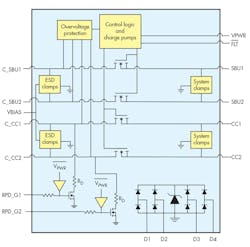
The solution is the TPD8S300 USB Port Protector (Fig. 5). It provides four channels of short-to-VBUS OV protection for the CC1, CC2, SBU1, and SBU2 pins, including protection against ringing. The part also protects these pins from ESD strikes, and includes an additional four channels of ESD protection for the two D+/D‒ pairs. The ESD protection meets the IEC 61000-4-2 standard.
The other device in the Figure 2 block diagram is the HD3SS460, a high-speed bidirectional passive switch that can act as either a multiplexer or a demultiplexer. Placed after the protection devices, the HD3SS460 provides crosspoint switching for the SBU signals to accommodate connector flipping. The device also facilitates Alternate Mode operation by allowing, for example, switching between four channels of video and two channels each of data and video.
Evaluation Module
Texas Instruments has developed a reference design and evaluation module (EVM) to help designers evaluate the TPS65983B in USB Type-C and USB PD applications. The TPS65983EVM allows for evaluation and testing of the component either as a standalone kit or as part of the development of USB Type-C end products.
Conclusion
The USB Type-C connector standard offers the promise of increased ease-of-use, ubiquitous high-speed data communications, and the integration of multiple incompatible standards into a single interface.
When combined with the new USB PD 3.0 specification, it ushers in a new design paradigm for power distribution in many lower-power devices, such as laptops, monitors, smartphones, hard-disk drives, and more.
These two developments raise the bar for designers of power systems, and especially for protection devices. The article has discussed some of the measures needed to accommodate the new standards and ensure robust protection against hazards such as pin-to-pin shorts and ESD. An evaluation board that demonstrates a USB Type-C port design is available.
As soon as our engineers can demonstrate a jump over an eight-foot bar, we’ll be sure to let you know.

About the Author
Paul Pickering
Paul Pickering has over 35 years of engineering and marketing experience, including stints in automotive electronics, precision analog, power semiconductors, flight simulation and robotics. Originally from the North-East of England, he has lived and worked in Europe, the US, and Japan. He has a B.Sc. (Hons) in Physics & Electronics from Royal Holloway College, University of London, and has done graduate work at Tulsa University. In his spare time, he plays and teaches the guitar in the Phoenix, Ariz. area
Comment About the Article
To join the conversation, and become an exclusive member of Electronic Design, create an account today!

Leaders relevant to this article: