Reap the Benefits of Economizers for Solenoid/Relay Drivers

Download this article in PDF format.
When I think of economizer circuits for solenoids and relays, I’m reminded of the phrase, “you can’t have your cake and eat it, too.” This phrase comes to mind because if you use a solenoid economizer, it doesn’t apply!
In engineering, as in baked goods, there are always tradeoffs that affect your decisions. While you can’t have your cake and eat it, too, you can use an economizer for a strong initial pull-in force while still driving your solenoid with low current in the long run.
The Physics
If I want to have a strong pull-in force for my solenoid, I need to drive it with a large current. That’s because the strength of the magnetic force is proportional to the current squared. At the beginning of the solenoid’s stroke, the armature or plunger has to overcome friction and spring force. In addition, the force at the beginning of the stroke is weak because it depends on the size of the gap (see equation below). This is why a large current is required for initial pull-in.

The equation approximates the force of the solenoid. N is the number of turns, A is the cross-sectional area of the plunger, g is the gap size, μO is the magnetic permeability of air, and i is the current. Because the solenoid force depends on gap size and current, when the gap size is small, the force becomes large. This means that you need less current to hold the solenoid in place, even with the same force requirements.
Economizer Circuits
A solenoid economizer circuit supplies large current initially during solenoid pull-in, then drops the current to a lower level to hold the plunger in place. This is how you can have your cake and eat it, too. You can implement economizer circuits with passive components, dedicated integrated circuits, or microcontrollers. Some common descriptors of the economizer function include:
- Peak and hold
- Spike and hold
- Pull-in and hold
- Solenoid economy circuit
- Energizing current and hold current
Spike and Hold
Spike and hold usually describes a simple economizer circuit that uses an external resistor and capacitor. The transient response of the capacitor causes the “spike.” Once the capacitor is fully charged, the current through the coil reaches a lower steady-state value. This provides some power to be saved in the hold region. The circuit and scope shot in Figure 1 are from Paul Rako’s Electronic Design article on solenoid driving techniques, which he learned from Bob Pease.
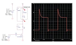
1. This spike-and-hold circuit was developed by Bob Pease.
While the spike-and-hold circuit is simple, the power dissipation of this configuration is still fairly high. The power dissipated from the added external resistor is almost the same amount of power dissipated by the solenoid itself (Paul recommends choosing an external resistor rated at 80% of the solenoid resistance). For this configuration, you get to eat some of the cake, but you only get to have half of it.
PWM Driving
Just as pulse-width modulation (PWM) is used to drive motors, it’s also able to drive solenoids. The economizer function can be done in firmware with a microcontroller or a dedicated integrated circuit (IC) (Fig. 2).
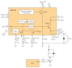
2. Shown is a DRV104 PWM solenoid economizer (top), and a microcontroller driving a solenoid with PWM (bottom).
To implement the economizer, turn on the driving transistor for a predetermined amount of time to ensure solenoid actuation (pull-in). After that amount of time, the economizer will output a PWM signal to reduce the current in the coil. Figure 3 shows the current and voltage driving outputs for the PWM implementation.
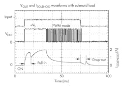
3. Here’s an example of solenoid economizer voltage and current outputs using PWM (from the DRV104 datasheet).
Current Control
You can further improve the performance of a solenoid economizer circuit by using current-sense feedback to implement current control. As shown in the equation, the force of the solenoid is proportional to the square of the current. A large current is required to produce a strong magnetic force when the plunger gap size is large. After the gap is closed, the magnetic force is large, and less current is required to hold the plunger in place. Figure 4 shows an example circuit that might be used in a three-phase contactor. Figure 5 reveals the peak-current and hold-current profile from the current-controlled economizer.
Current control has two main advantages: It’s reliable over temperature, and it works regardless of voltage supply. As the solenoid or relay coil heats up from I2R losses or is warmed by its environment, the coil resistance increases. If the solenoid is being driven by a fixed voltage or the open-loop PWM driving mentioned above, the current in the coil will decrease as temperature and resistance increase.
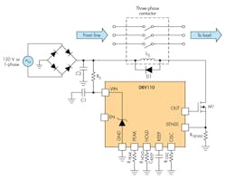
4. This current-regulating economizer incorporates the TI DRV110, which uses hysteresis control to regulate the current in the coil.
Since magnetic force depends on current, the solenoid or relay armature may deactuate as current drops. This could mean that a valve closes when it’s supposed to open, or that a relay opens when it should close. When monitoring the current in a closed loop, the economizer can adjust the PWM duty cycle to ensure a reliable solenoid force and current over temperature.
Sometimes a relay or solenoid has good performance but may not be rated for the voltage rails available in a system. Solenoids operate by current, but they can also be destroyed by too much current when using a voltage higher than the solenoid rating (think I = V/R with the solenoid’s series resistance). When the economizer circuit controls the current directly, it removes the risk for an overcurrent condition to destroy the solenoid. Furthermore, using closed-loop current regulation in this way means that you can use a single solenoid design in multiple products. My blog post, “Liberate your solenoid or relay from the bonds of supply voltage” describes these advantages in greater detail.
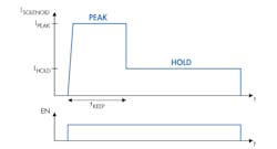
5. Shown is a peak-and-hold solenoid current sketch for the DRV110.
Conclusion
Economizer circuits embrace the physics of solenoids and relays to bring power savings and improved reliability to solenoid driving. They provide a large current initially to pull in the armature of a solenoid or relay. They then supply a lower current when the solenoid has a stronger magnetic field to save power during operation. While you may not be able to have your cake and eat it, too, you can bring reliability and power savings to your solenoid/relay-driving applications.
James Lockridge dedicates this article to the late Dr. Alan Kraft (Valpo professor and fellow Purdue grad), who inspired his interest in electrical machines.

About the Author
James Lockridge
Applications Engineer
James Lockridge is an applications engineer for TI's current-regulating solenoid driver and optical-disk driver products. He received his BSEE from Valparaiso University and currently is pursuing his MSE degree at Purdue University, focusing on electrical machines and controls.
Comment About the Article
To join the conversation, and become an exclusive member of Electronic Design, create an account today!

Leaders relevant to this article: