Download this article in PDF format.
FPGAs are a popular choice among engineers for digital design in a wide variety of applications. They’re an alternative to microcontroller design, which requires high speed in a dedicated function. In certain cases, FPGAs eliminate the need to create an expensive custom ASIC. Their low cost and range of sizes make them useful in industrial, medical, aerospace, defense, and even some consumer products.
But while engineers are happy with their FPGA design solutions, many quickly discover that it causes another problem. Some are surprised to find that each FPGA requires multiple, critical dc voltage supplies. Four to six or more dc rails are needed in many instances, creating a need for a special power supply solution. That’s usually a big problem, but there are ready-made answers to this knotty problem.
Sponsored Resources:
- TI Experts Talk FPGA Power
- Small, Efficient Power Supply Reference Design for Altera™ MAX® 10 FPGA for up to 125°C
- TI leads the way for power-hungry FPGAs
The Power Conundrum
Most products today use standard power rail voltages of 12, 5, and/or 3.3 V. On the other hand, if an FPGA has been adopted, the power-supply voltage needs are widely different. Rail levels as low as 0.72, 0.85, and/or 1.0 V at high current levels are required. Other common FPGA rail needs include 1.5 and 1.8 V, also at a relatively high current level. The lower voltages usually power the core of the device, while the other voltages serve the memory, transceivers, IO circuits, and auxiliary circuits.
This problem shows up when special high-speed processors are being designed in, too. Again, multiple low-voltage/high-current rails are needed.
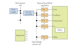
Besides the requirement for multiple rails, each has its own specifications for current, voltage accuracy, ripple, load transients, and sequencing. The figure shows common solution. One of the main power sources is stepped down with a dc-dc converter to form an intermediate rail. Then the individual power rails are created with a point-of-load (POL) regulators, switchers, or LDOs as seen fit. And a sequencer is essential.
FPGAs are typically powered by individual POL regulators driven from a common power rail.
With regard to voltage accuracy, the FPGA core and transceivers usually require 3% or better. Accuracy for IO and auxiliary supplies are typically less than 5%. Voltage tolerance range should be less, too—that range is made up of ripple around the set-point voltage plus the regulation percentage. Ripple levels are specified for the device used. Then there’s the tricky sequencing problem. The supplies positively must be turned on and off in a prescribed sequence. The usual requirement is core supply comes first, transceivers at the same time, and then auxiliary circuits followed by IO circuits.
There are multiple ways to sequence the supplies. You can use RC network delays, having one supply enable the next supply, or by controlling the whole thing with an available microcontroller using its timers and GPIOs. However, the best solution is to use an IC specially designed for the job.
The Easy Way Out
If you’re a digital designer looking for a fast and simple solution to the multi-rail power problem, you can seek out ready-made products that directly address your power needs. Texas Instruments is one vendor of power products with multiple solutions.
The quickest choice is to use a power module. An example is TI’s LMZ30602 power module that combines a 2-A dc-dc converter with power MOSFETs, a shielded inductor, and passives into a low-profile, 9- × 11- × 2.8-mm QFN package. This IC requires only three external components and eliminates the loop compensation and magnetics part of the design process. Just add capacitors and voilà. Other modules in this series have a wide range of input-rail voltages, output voltages, and current ratings.
Another solution is to seek out available reference designs. TI offers several of these, such as the TIDA-01366 (also known as PMP9799), a complete power solution for Altera's popular MAX 10 FPGA. This simple solution uses just three dc-dc converters to power the MAX 10 efficiently (89% to 92%) and cost-effectively. The TI design supports numerous industrial applications and any application that requires a small, high-efficiency, high-temperature power supply. Another TI reference design addresses the needs of Xilinx’s Ultrascale/Ultrascale + FPGA products.
Also don’t overlook available vendor design tools. One of these is TI’s WEBENCH FPGA Power Architect. It will take your requirements and walk you through to a solution with specific parts recommendations.
If you’re designing your own supply with dc-dc converters, take a look at the Texas Instruments’ LM3880 simple sequencer to solve the turn-on timing problem.
For you digital designers, continue to enjoy the benefits of your FPGA and the comfort that comes from knowing that power-supply solutions are readily available.
Sponsored Resources:

