Understanding the Pros and Cons of Overvoltage Protection
When testing your devices, it may become apparent that the device needs protection against an overvoltage condition. Most power supplies offer some form of overvoltage-protect (OVP) circuit. The OVP circuit’s purpose is to detect and then quickly pull down the overvoltage condition to prevent damage to your device under test (DUT). However, it’s important to understand how your power supply’s OVP works to maximize its benefits.
This file type includes high resolution graphics and schematics when applicable.
What Causes Overvoltage?
The power supply itself could be the source of the overvoltage. A failure inside the power supply may force an unexpected and uncontrolled high voltage across the DUT. It’s also possible that the overvoltage is not due to a power-supply failure, but some user error where the user programs the power supply higher than the DUT can tolerate.
The overvoltage condition could come from outside of the power supply. The DUT can be subjected to overvoltage because wires inside a connector or wiring harness short together, placing high voltage on the DUT. Or, a switch matrix may fail or be programmed incorrectly, placing high voltage on the DUT. In these cases, the power supply’s OVP circuit will come to the rescue. If the detector sees a voltage higher than the set OVP threshold, the OVP fires, and the power supply attempts to remove the overvoltage from the DUT.
How Does OVP Work?
OVP circuits can be fixed or tracking and local or remote. A fixed OVP makes it possible to set a fixed voltage threshold, either manually or programmed remotely. It’s a fixed value such that when the power-supply output voltage exceeds this value, the OVP circuit trips and the power supply tries to pull down the overvoltage on its output. The power supply output voltage can be changed, and the OVP threshold stays the same.
A tracking OVP allows you to set a threshold value that varies with the output voltage. For example, the tracking OVP might be set to 0.5 V, or 10%, over the programmed output voltage. Thus, the OVP is always above and tracks the output setting. While this sounds good, a problem arises: If you program the wrong value on the power supply, the OVP is also programmed wrong. If you meant to program 2.5 V and accidently programmed 25 V, then the OVP will be set above 25 V and it will not protect against this user-inflicted overvoltage condition.
A local OVP monitors for the overvoltage condition on the output terminals of the power supply. A remote OVP monitors for overvoltage condition at the remote sense point of the power supply. (For more information about remote sensing, see “Remote Sensing Improves Voltage Sourcing at High Current.”)
False Trips vs. Undetected Real Overvoltage Conditions
It’s desirable to have overvoltage protection, but if the OVP is able to be falsely tripped, it quickly becomes a nuisance. On the other hand, though, if the OVP can possibly miss a real overvoltage condition, then that becomes hazardous. Let’s look at how each type of OVP fares with respect to false trips or undetected overvoltage events.
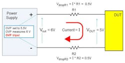
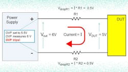
Fixed-local OVP (Fig. 1): This is the most common implementation of OVP. Imagine you have long wires out to the DUT, which means a large voltage drop in the wires. If you want 5 V at the DUT, but there’s 1 V of drop in the wires, the power supply will need to produce 6 V to drive 5 V at the DUT. So what do you set the OVP threshold level? If you want overvoltage protection at 5.5 V, the OVP will false-trip because the local OVP will see 6 V when the DUT is at 5 V. A solution could be to set the OVP to a level higher to prevent the false trip, but that offers less protection. Another solution would be to detect the overvoltage remotely at the DUT (i.e., the remote sense point), rather than detect locally at the power-supply output.
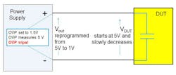
Tracking-local OVP (Fig. 2): Imagine you have a large capacitor in the DUT, and the tracking-local OVP is set to 0.5 V above the programmed voltage. You’re sourcing 5 V on the DUT, so the tracking-local OVP is set to 5.5 V. Now, you want to reprogram down to 1 V, so you set the power supply to 1 V and the tracking-local OVP goes to 1.5 V. But the large capacitor in the DUT still has 5 V on it, since it takes time for the capacitor voltage to drop. However, the OVP circuit sees greater than 1.5 V and falsely trips due to the momentary (and expected) overvoltage. A solution in this case could be to put in some kind of delay to allow the capacitor to discharge, but this delay means there’s a stretch of time when the DUT is unprotected.
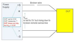
Tracking-remote OVP (Fig. 3): So, a tracking OVP (with delay) takes care of your changing voltages during the test and the remote takes care of lead losses. Thus, a tracking-remote OVP (with delay) sounds like the best of both worlds. However, now you’re relying on the sense lines to operate properly to protect the DUT. Is that a good idea?
Remote sense lines often break in a test system. Without sense leads, the output voltage will typically rise on a power supply (there’s no feedback through the sense lines because the sense lines are broken). The rising voltage causes an overvoltage condition. But because the sense lines are broken, the OVP circuit doesn’t detect the overvoltage condition and, therefore, no OVP shutdown. While a tracking-remote OVP seems to be the solution for false trips, it creates the possibility of an undetected real overvoltage condition when breakage occurs in the remote sense lines.
This file type includes high resolution graphics and schematics when applicable.
Summary
Protecting your DUT always involves a tradeoff between the highest level of protection and false trips of an OVP circuit. Understanding how OVP works and when it may falsely trip or miss an overvoltage helps pinpoint the right OVP method to protect your DUT based on what may happen in the test environment.
About the Author

Bob Zollo
Solution Architect for Battery Testing, Electronic Industrial Solutions Group
Bob Zollo is solution architect for battery testing for energy and automotive solutions in the Electronic Industrial Solutions Group of Keysight Technologies. Bob has been with Keysight since 1984 and holds a degree in electrical engineering from Stevens Institute of Technology, Hoboken, N.J. He can be contacted at [email protected].
Comment About the Article
To join the conversation, and become an exclusive member of Electronic Design, create an account today!

Leaders relevant to this article: