Understanding Signal and Power Isolation Techniques

This article is part of the TechXchange: Delving into Digital Isolators
Download this article in PDF format.
Electronic isolation is a means of preventing the transfer of direct current (dc) and unwanted alternating current (ac) between two parts of a system while still enabling signal and power transfer between those two parts. This kind of isolation is required in a number of instances, such as:
- Protecting industrial operators from high voltage.
- Protecting expensive processors and related circuits from high voltage.
- Preventing ground loops in communications networks.
- Improving noise immunity.
- Communicating with high-side devices in a motor drive or power-converter systems.
Industrial equipment that requires isolation includes programmable logic controllers (PLCs), motor drives, medical equipment, solar inverters, electrical vehicles (EVs), and some special power supplies.
There’s a need for an efficient, affordable, and compact isolation solution for industrial equipment. A fully integrated signal and power isolation product that’s now available brings a number of benefits to system design, including reduced board space, ease of certification, and simpler design. This article introduces isolation methods and a modern integrated approach.
Isolation Methods
One rather obvious method of electrical isolation is to use a transformer. The primary and secondary windings are electrically separate, and power transfer is strictly by way of magnetic induction rather than current flow. A transformer is still a key part of isolation methods, and is the approach of choice for dc power isolation.
While transformers can be used for signal transfer, they’re limited in speed, and are bulky and expensive. Other choices are available, though. One isolation method that’s been around for years is optical isolation, and it involves an integrated circuit called an optocoupler. It’s made up of an infrared LED and phototransistor, usually a BJT with an open collector. In some devices, a separate photodiode detector is used (Fig. 1).
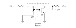
1. An optocoupler uses an IR LED and a phototransistor to provide a signal path, but with high-voltage isolation.
With no input signal, the LED is dark and the phototransistor is off, so the external pull-up resistor produces a high output. When an input signal is applied, the LED turns on, the base of the phototransistor is illuminated, and it produces the bias that turns the transistor on. This causes the output to go low.
Optocouplers work well and provide good high-voltage isolation up to 5 to 10 kV. Their main disadvantage is speed of operation in some digital systems. Today, a newer form of isolator using capacitive connectivity is now available.
Digital isolators use silicon-dioxide dielectric capacitors as the isolation method. However, because the capacitance is restricted by the physical limitations of an integrated circuit, special techniques are used to ensure the fast transfer of energy. One technique is edge-based and the other employs on-off keying (OOK) modulation.

2. The edge-based method of isolation uses two paths, one for slow data and the other for high-speed data. (Source: Texas Instruments)
A typical digital isolator is made up of a transmitter (TX) section and a receiver (RX) section. They’re isolated by the capacitive coupling. Figure 2 shows the edge-based method. A single-ended input signal to be transmitted is first converted into a balanced signal that then passes through the isolation capacitors. In the lower path, the received signal is differentiated into narrow pulses. Comparators and a flip-flop process these pulses into pulses that are applied to a multiplexer (MUX), which provides the output.
Note that the input signal is also sent to the upper low-speed path, where it pulse-width modulates a higher-frequency oscillator. The pulse-width-modulation (PWM) signal is converted to a balanced signal and passed through the isolation capacitors, where it’s processed back into pulses. A low-pass filter (LPF) filters out the high-frequency PWM and recovers the original signal. If the input signal is too low in frequency, a decision logic circuit (DLC) detects the situation and switches the multiplexer to the low-frequency path.
Figure 3 shows the OOK method. The single-ended signal is sent to an AND gate along with an oscillator using spread-spectrum techniques to modulate the input. The resulting higher-frequency signal is converted to balanced form and passed through the isolation capacitors. On the receive side of the IC, the signal is conditioned and amplified. Then an envelope detector extracts the original signal for output.
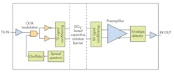
3. The on-off keying (OOK) method of isolation uses modulation to transfer signals through the capacitive paths. (Source: Texas Instruments)
Isolation Examples
A good example of a need for isolation is that of a PLC in a factory-automation setup. PLCs are widely used in industry to monitor and control a variety of machines. The PLC gets its inputs from sensors that measure temperature, pressure, position, and other physical characteristics. These sensors are commonly remote from the PLC itself, meaning long cable runs. This situation usually creates ground potential differences that can skew sensor data and introduce errors. Some form of isolation is needed to ensure accuracy.
Figure 4 shows how isolation is achieved. The sensor signal is usually conditioned by filters, protection circuits, and an amplifier. The resulting analog signal is digitized by the ADC. This is the data signal that’s needed by the PLC processor to make its decisions. Note that a capacitive-coupled digital isolator is used to eliminate any errors due to ground loops.
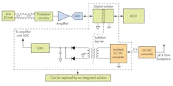
4. This isolation example shows signal and dc isolation in an industrial PLC. (Source: Texas Instruments)
The other part of the isolation is the dc power to signal conditioning circuits. The dc power for the signal conditioning circuits and ADC is derived from the 24-V rail in the PLC. A dc-dc converter converts this into 5 V that operates a dc-dc converter, producing pulses that are transferred by an isolation transformer to a dc supply and LDO that furnishes the voltage for the signal-conditioning circuits. Note that the isolation circuits within the dashed lines are those that can be packaged as an integrated solution.
Another application example is the need to isolate one system from another while providing communications between the two. PLCs, computers, special controllers, and other equipment are required to talk to one another for automation purposes. The RS-485 interface standard is widely used for such communications.
This application uses a differential twisted-pair cable in runs that can be as long as 4000 feet. Such long runs are subject to all sorts of noise pickup and can interfere with operations. The differential signals help mitigate noise, but it’s still a problem. Ground loops are another issue. The solution is digital and power isolation of the RS-485 interface shields the processors from any possible noise and high-voltage signals.
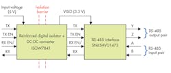
5. Here, a digital isolator device with a RS-485 interface is used for isolation. This combination represents Texas Instruments’ TIDA-00892 reference design. (Source: Texas Instruments)
Figure 5 shows how a digital isolation block processes the data signals for transmission and produces the dc power to supply the RS-485 interface circuits. This configuration, available as a reference design from Texas Instruments, provides a compact solution capable of generating isolated dc power while supporting isolated RS-485 communication. The design consists of the ISOW7841 reinforced digital isolator with integrated power combined with an RS-485 communication transceiver (SN65HVD1473).
As the demands increase for industrial applications, it generally means that more features to the system need to be added. This puts more pressure on the power-management system to power the various circuits for optimum performance without raising equipment temperatures. Many of these industrial applications also require data and power isolation to protect the low-voltage side from the high-voltage side of a system.

About the Author

Lou Frenzel
Technical Contributing Editor
Lou Frenzel is a Contributing Technology Editor for Electronic Design Magazine where he writes articles and the blog Communique and other online material on the wireless, networking, and communications sectors. Lou interviews executives and engineers, attends conferences, and researches multiple areas. Lou has been writing in some capacity for ED since 2000.
Lou has 25+ years experience in the electronics industry as an engineer and manager. He has held VP level positions with Heathkit, McGraw Hill, and has 9 years of college teaching experience. Lou holds a bachelor’s degree from the University of Houston and a master’s degree from the University of Maryland. He is author of 28 books on computer and electronic subjects and lives in Bulverde, TX with his wife Joan. His website is www.loufrenzel.com.
Comment About the Article
To join the conversation, and become an exclusive member of Electronic Design, create an account today!

Leaders relevant to this article: