Use Current to Drive Solenoid, Relay from Array of Voltages (.PDF Download)
Relays and solenoids are available with many different voltage ratings. Most factory- and process-automation equipment operates from 24-V supplies. However, customers may have control signals for a wide range of ac or dc voltages, such as 12 V, 24 V, 36 V, 48 V, or even 120 V or 220/240 V for some valves and contactors. For each voltage, the coil designs of the variants must be different. Having coils to accommodate all of the possible voltage adds to inventory, BOM, and spare-part headaches.
One solution could be to design one coil for 12 V, then use a resistor to limit the current into the coil for each voltage option. However, this wastes energy and dissipates heat from the resistor, especially if the 12-V coil is used for the 220/240-V design.
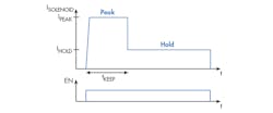
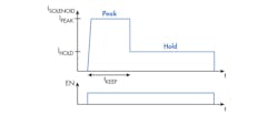
1. Here’s an example of how current shaping with PWM can save power in the long term.
A more energy-efficient solution is to use pulse-width modulation (PWM) driving and a freewheeling diode to regulate the current in the solenoid. In addition, you could add current-sense feedback with PWM and control the current in the solenoid. Using a PWM driving method can also allow you to shape the current-drive profile to have a higher pull-in current for actuation, then drop to a lower current to hold the solenoid in place and save power in the long term (Fig. 1).
