Here are some additional comments on the K2-W that did not fit in What's All This K2-W Stuff, Anyhow? | Electronic Design (Electronic Design, Jan. 6, p. 20). The K2-W had adequate gain and dc stability, and it was fast enough for many analog computing schemes—100 times faster than the M-IX amplifier mentioned in Part 1.
Uses: George A. Philbrick Researches, at 127-129 Clarendon St., implemented hundreds of K2-W's each month in the popular analog computing modules, such as the K5-U, K5-M, and so forth. That got the production volume up.
What if you did not like the offset drift to be ±50 mV per day? Philbrick would be happy to sell you an add-on K2-P Chopper-Stabilizing Amplifier, to cut the drift to below 1/2 mV per day—and that's not too bad stability referred to full scale! It was priced at$54.
What if you wanted more output swing than the paltry ±50 V? For $33, you could swap in, to the same socket, a K2-X or K2-XA that would swing ±100 V at up to 3.3 mA. Not too poor. In fact, many modern operational amplifiers are not rated to drive 330 mW!
A $400 R-300 power supply would provide enough power for 70 K2-W's, so the 'W really was light on its feet in terms of power needs.) One reason why the R-300 was so good in its accuracy and stability was so that it could compensate for the K2-W's lousy PSRR. This ALSO was never specified, but it was about 18 dB.
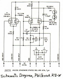
Note: Walter Jung has written a very good chapter on the history of op amps, in a new book, Op Amp Applications, published by Analog Devices. The cost is $22. That's no more than the price of a K2-W! The chapter includes Walt's comments on the K2-W, plus a photo and schematic of the unit.
A SUSPICION NOT UPHELD: I finally got some data on the K2-W. I was really expecting Zout to be lousy, worse than the data-sheet value of 1 Ω, because the K2-W's gain of 10,000 minimum does rely a lot on the Positive Feedback from the 221 k resistor. I was thinking that the output did not have much gm. But actually, the cathode-follower output did a pretty good job. Zout (closed-loop, as a unity-gain follower) was about 0.24 Ω. So I'm pleased to see where my erroneous thinking was corrected!
Note: In the schematic, the balanced input stage went to a single-sided level shifter down to the grid of the second stage, down near +2 V. This stage gets positive feedback from the output follower, via 221 kΩ, which was required to get the gain up from 4000 to 20,000. Note also the 15-pF Miller capacitor around the second stage, and the two NE-2 neon lamps used as level-changers to the grid of the output follower. (The op amps in the Heathkit analog computer were the same, except they used three 52-V zeners—Ha!
WHAT ABOUT THE PACKAGING? The components of the K2-W were ingeniously hay-wired over a jig. Of course, everything was carefully hand-soldered. Then it was closed up inside two plastic shell halves. The K2-W's octal base plugged into the user's socket, and the nine-pin tubes plugged in at the top. The whole thing stood just 4.1 in above the chassis. Not bad for $22.
Comments invited! [email protected] —or:
Mail Stop D2597A, National Semiconductor
P.O. Box 58090, Santa Clara, CA 95052-8090
About the Author

Bob Pease
Bob obtained a BSEE from MIT in 1961 and was a staff scientist at National Semiconductor Corp., Santa Clara, CA, for many years. He was a well known and long time contributing editor to Electronic Design.
We also have a number of PDF eBooks by Bob that members can download from the Electronic Design Members Library.


