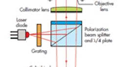
CD pickup head-based measurement device
The ability to measure the displacement of a moving target with extremely high accuracy is often indispensable in applications such as micro positioning, accelerometers, micro cantilevers, and the alignment of small objects. Systems based on laser interferometer and capacitive sensors are unattractive for many applications, however, due to their complexity in assembly. A simpler alternative can be implemented by using a pickup head from a compact disc (CD) system.
A CD pickup head design (see the figure) consists of an optical laser, a holographic grating for a position reference, a lens system with voice-coil focusing control, and a quadrant photo diode for determining when the reflected back image is in focus. In this design, a Cypress Micro Systems programmable system-on-a-chip (PSoC) controls the pickup head and makes the micro-position measurement.
The head assembly collimates and focuses the output of a laser diode onto an object surface. The reflected beam passes back through the lenses and through an astigmatic beam-shaping lens onto a photodiode integrated chip (PDIC). Four quadrant photodiodes (A, B, C, and D) comprise the PDIC’s center, and each connects to a current preamplifier. When the object surface is exactly at the laser beam’s focus point (defocus distance = 0), the light spot on the photo-detector is circular. Raising or lowering the surface relative to the focus point elongates the spot in the AC or DB direction, respectively.
The shape of the light spot at the PDIC forms the basis for a focus error signal (FE), which is defined as (A + C) − (B + D). The values A, B, C, and D are the preamplifier output voltages of photodiodes A to D, respectively. For a circular light spot, the error signal FE = 0.
The PSoC receives the photodiode signals (A + C) and (B + D), amplifies them, and feeds them into a 12-bit incremental analog-to-digital converter (ADC) for digital conversion. A control program, written in LabVIEW, senses the FE value from the quadrant photodiode and adjusts the drive signal for the voice coil until FE = 0, which occurs when the spot is in focus on the target object. The drive signal comes from the PSoC’s internal 16-bit pulse-width modulator (PWM) and an external RC circuit. Together, the two elements function as the equivalent of a 16-bit digital-to-analog converter (DAC) feeding the coil’s drive transistor.
After the sensor has initially focused on the target surface, any subsequent movement of the surface will trigger a corresponding change in the PWM’s control setting. The difference between the initial and new settings serves as a measure of the target’s displacement. The polarity of the difference indicates displacement direction. After calibration, the microcontroller can convert these difference values to displacement measurements. The microcontroller can also send the sensor ADC’s output through the UART block to a PC for additional analysis.
The measurement range for this system is small because the pickup head’s design only needs to handle normal variations in the position of a CD’s reflective layer. The resolution, however, is excellent. Our detection system, based on modification of a commercial CD optical head, achieved a resolution better than 2 µm in detecting the target’s displacement.
