In low-power USB and offline wall adapters, quasi-resonant and discontinuous current mode flyback converter topologies are a popular choice due to their low parts count and relatively low cost. However, to increase profitably in the adapter market, power supply manufacturers continuously are working on ways to reduce design cost. This article discusses a voltage and current sensing technique (Fig. 1) that removes the need for an optoisolator and an adjustable precision shunt regulator like the TL431 feedback network. This reduces the total parts count, and in turn should reduce the overall design cost.
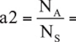
Traditionally these isolated flyback converters sense the output voltage for primary control with an optoisolator and regulator feedback circuitry, presented in Fig. 1 (circuitry is RED). However, in these inexpensive flyback converters, typically the controller circuitry is powered up with an auxiliary winding off the transformer (T1, NA, Fig. 1). The output voltage can actually be sensed (VS) off the auxiliary winding through the secondary transformer turns ratio (a2), removing the need of an optoisolator and regulator feedback circuitry. This removes six components from the design, which in turn reduces the design cost. Note in Equations 1 and 2, VA is the connection between the auxiliary winding and diode DE and resistor RS1.
Where:
VDG = Forward voltage drop across diode DG
VS = Sensed output voltage
Based on volt-second balance, the turns ratio of this flyback converter can be described as:
Where:
VB = Input to the flyback converter
tON = On time of FET QA
tC = Conduction time of output diode DG
LPM = Transformer T1’s primary magnetizing inductance
LSM = Transformer T1’s secondary magnetizing inductance
The output voltage can be sensed from the auxiliary winding, as well as the input voltage (VB). This can be accomplished through the primary to auxiliary turn’s ratio (a3). It is a negative voltage and can be sensed through level-shifting circuitry. Information about the input voltage can be used to determine if the converter should be allowed to operate or shut down. This signal can be used to control input under voltage lockout circuitry.
Removing the regulator’s opto feedback scheme does not come for free and presents a few design challenges. First, signal VA needs to be as clean as possible. This may require a snubber network across diode DG to remove ringing on VA. This is not uncommon in flyback converters, and is just two passive components. Generally, 100 mV of ringing on VA is acceptable in these designs.
Second, the transformer in the real application is not ideal. There is primary leakage inductance (LPLK) which generates voltage spikes at the switch node coupled from the primary to the auxiliary winding (VSPK) though the primary to auxiliary turns ratio (a3). Fig. 2 shows a transformer model. If this leakage spike is not dealt with properly, it could cause output voltage regulation issues in the power supply.
Where:
VLM = Voltage across LPLK
When designing a flyback converter for this application, it is important to select an integrated controller designed for this application. Otherwise, the designer will find themselves adding discrete circuitry to the design to deal with the voltage spike that occurs at the auxiliary winding output (VA). This extra circuitry adds components to the design and, most likely, will nullify the cost savings by removing the regulator feedback scheme.
Several controllers exist on the market for this application, including Texas Instruments UCC28700 flyback controller. This controller was designed to control the output current and output voltage from the transformer’s primary. It senses the output voltage on the primary auxiliary winding with sample and hold circuitry. This circuitry has 500 ns to 1.5 µs of blanking (tB) where the auxiliary voltage is not sensed, so the leakage spike voltage is ignored in regards to the voltage feedback loop. The following waveform shows the voltage at the auxiliary winding (VA), the current sense signal (RCS), and the controller’s gate drive (DRV) when the flyback controller is operating near critical conduction with valley switching. When VA transitions high, the blanking time (tB) is initiated and the auxiliary voltage is not sampled during time interval tB. In the waveform in Fig. 3, the duration of the leakage spike is represented by variable (tLK).
The UCC28700, after tB has timed out, samples the output voltage through the VS pin at the end of tS. This voltage then passes to the error amplifier to control the peak input current and flyback converter’s duty cycle that regulates the output voltage. If done correctly, the designer should be able to precisely regulate the output voltage using this technique, as shown in Fig. 4.
A converter like the UCC28700 also senses the input voltage by sensing the current through RS1 during the transformer energizing period when FET QA is on. This current is then sent through a current mirror to hysteretic line fault comparator to detect for an under voltage condition. If during a negative transition on the VS pin the RS1 current (IRS1) magnitude is not greater than 220 µA, an input under-voltage condition is detected and the line fault circuitry is activated.
In USB and low power adapters, quasi resonant flyback converters can be utilized for the design without the need of a TL431 opto feedback network by sensing the output through the transformer turns ratio. In these applications, removing this feedback circuitry can reduce the cost of the design.
References:
UCC28700 and TL431datasheets
Related Articles:
Improving the Performance of Flyback Power Supplies
Gain Equalization Improves Flyback Performance
