Courtesy of XP Power
Specifying an ac-dc power supply for systems with peak load requirements that are higher than the normal power requirements for short periods can result in larger, higher-power, and higher-cost product selection.
In these applications, the average power required is typically significantly lower than the peak demand and, with care, savings in product size and cost can be realized without compromising system reliability or lifetime. Using a power supply that is capable of supporting the peak load but with a lower continuous power rating will result in a physically smaller power supply reducing system size, weight, and cost.
For example, in a system that requires 300W for a short duration, using a 200W continuously rated power supply that can support a 300W+ peak load will result in significant savings in volume and cost over a supply rated at 300W continuous output power, provided that the average load is below 200W. The supply must be electrically rated to safely support the peak demand, but can be thermally rated at the lower power level.
Applications that require higher peak currents often include some electromechanical elements such as print heads, pumps, motors, and drives. These products have average power demands far lower than the peak power requirements and are found in factory automation, medical devices, fluid and material handling, robotics, power tools, machining, packaging, test, dispensing systems, and printers.
Some products specify a peak load capability, which can be characterized in a number of ways:
A power supply is rated for up to 30 seconds with a duty cycle of 10 to 15% at a peak load that is just below the overcurrent protection (OCP) limit. The OCP is usually set around 20 to 30% above the continuous current rating. This is essentially a standard design, evaluated and characterized to give short duration headroom over and above the nominal continuous rating. There are applications where an additional 20-30% of power is required for short durations. These are typically electromechanical applications that demand higher peak current for a shorter duration. Taking advantage of these characteristics to support occasional peak power demands results in a smaller, lower cost supply, but the average power demand must be kept below the maximum continuous rating.
A very high peak of up to 200% of nominal for a very short duration where the OCP does not react to the overload condition. Typically, this allows peak current handling for 200-500 μs. This type of peak capability covers a limited range of applications.
A higher power rating at high-line, normally meaning 180 VAC and above. For example, a 1200W power supply may be able to provide 1500W of continuous power when operated at an ac input voltage greater than 180 VAC. This is a genuine size and cost benefit if the ac input is in the high-line range and is ideal for higher power systems connected from phase to phase when the nominal single phase supply is low.
A power supply with the topology and thermal characteristics, designed to support high peak electromechanical loads. Such units may deliver up to twice their nominal power for 10 seconds or more with duty cycles up to 35% for demanding electromechanical applications in industrial process control. XP’s fleXPower modular power system is one example that allows several standard outputs alongside one that provides a high peak current.
Often overlooked when considering peak load applications are power supplies with a convection rating and a higher fan cooled rating. It is not uncommon for such a supply to be rated at up to 50% higher power when fan cooled compared to a naturally cooled environment. These products are generally of open frame or U channel construction and cover power ranges up to 500-600W. Such products are naturally electrically rated for the fan-cooled power rating and thermally rated for the convection cooled power rating.
In general, the larger the difference between the fan-cooled rating and the convection rating, the shorter the peak load capability. A benefit for the system designer is that these dual-rated products will normally identify key components and their temperature ratings to ensure safe and reliable operation when installed in end applications. This information can be used to ensure that the product will remain safe and reliable in a peak load application by monitoring the temperature of the key parts during the development phase.
The specification will also typically outline the lifetime expectations based on key electrolytic capacitor temperatures, enabling confirmation of the suitability of the product based on system requirements.
When selecting a power supply for a high peak power application, based on the force cooled and convection cooled ratings, the key parameters are the peak power required, which must not exceed the fan-cooled rating, the maximum duration of the peak, the duty cycle and power consumed by the load during the non-peak duration to ensure that the continuous convection ratings of the supply are not exceeded.
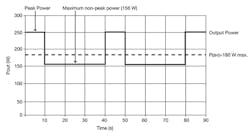
Figure 1 is based on an open-frame power supply with a force cooled rating of 250W and a convection or naturally cooled rating of 180W, XP Power’s GCS250 series, operating in a convection cooled application where the system requires a peak load of 250W for 10s in every 40s or a duty cycle of 25%. This peak load (PPK) requirement defines the absolute maximum power consumption during the non-peak period so that the average power does not exceed the convection cooled rating.
In this case, the maximum available power during the non-peak duration (PO) will be 156 Watts in order that the convection cooled power rating (PAV) is not exceeded.
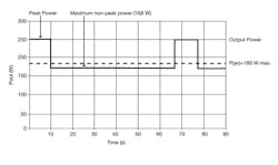
Using the same formula, if the duty cycle is reduced 15%, or 10s in every 67s then the non-peak power can be increased to 168W without exceeding the average continuous convection power rating of 180W. This is shown in Fig. 2.
Where:
PAV = Average power
PPK = Peak power
PO = Non-peak power
T1 = Peak power time duration
T2 = non-peak power time duration
Calculations show that these operating conditions will not exceed the ratings of the power supply. However, as previously highlighted, we must also consider the key component temperatures of the supply when installed in the unique end equipment to ensure safe, reliable operation over the design life of the end equipment.
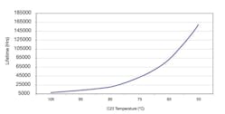
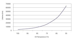
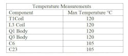
Table 1 lists the maximum temperature of the components for this product to ensure that the safety and reliability requirements are met. The predicted service life of the product is based on the average capacitor operating temperature over the life of the equipment as shown in Figs. 3 and 4.
In order to ensure safe operation of the PSU in the end-use equipment, the temperature of the components listed in Table 1 must not be exceeded. The temperature should be monitored using K type thermocouples placed on the hottest part of the component (out of direct air flow).

